


Text and jpegs by courtesy of hathitrust.org www.hathitrust.org, compiled by motorracinghistory.com
Motor Age, Vol. XXIII (23), No.19, May 8, 1925
Wire Wheels Return After 20 Years
Foreign-Made Wheels – Part III
By H. A. Tarantous
IN Europe the wire wheel has flourished more than it has in this country. In England the majority of the passenger cars are wire equipped and even in France there are a large number, although the latter country has been slow to adopt the device, believing until recently the wooden wheel more efficient than the wire.
With the perfection of the wheel abroad and its ultimate approval by most of the car manufacturers its fame has spread to this land and the types manufactured in this country differ only slightly from those made abroad, America in a sense taking dictation from the foreign makers.
Abroad exhaustive tests have been made, principally by the Rudge-Whitworth Co., the results of which were sent broadcast. It has been shown by this company’s laboratory work that the wire wheel is able to withstand the enormous strains to which it is subjected on the motor car. It is natural that England should be first to adopt wire wheels because of the fact that the Rudge-Whitworth Co. is an English concern. France, on the other hand, did not rely upon the English laboratory test alone, but to prove the wire wheel efficient fitted a number of cars with them and sent them on the road.
Perhaps the feature to the Frenchmen was the tire-saving ability of the wire wheel, but only after it showed that it could withstand the great weight of the motor car and do as well in service as the wooden, did the French car manufacturers adopt the wire wheel as stock equipment.
Although England is leading in the number of wire wheels in use on stock cars, the other European countries are following and within a very short time it is expected that 90 per cent of the European cars will leave the factory wire-equipped. This percentage is in no way a certainty, but according to the present rate of advance, together with the statements of the manufacturers of such types of wheels, the time is not far off when the wooden wheel will be discarded entirely on the other side.
One of the largest manufacturers of wire wheels in Europe is the Rudge-Whitworth Co., whose wire wheels are made in double-spoked and triple-spoked forms. The triple-spoked wheel is slightly stronger than the double-spoked wheel.
Rudge Whitworth Types
For the season of 1913, Rudge-Whitworth has brought out a new detachable wheel which differs from previous constructions in that a new locking arrangement is provided which greatly simplifies the attachment and removal of the wheel. The new locknut, by virtue of its contact with the inner hub and with shell of the detachable wheel has no tendency to come undone when once tightened, and will, in fact, tighten itself when the car is in operation. Fig. 2 shows a section of a wheel in place on its inner hub; A is the inner hub, B is the detachable shell, and C is the lock nut.
An examination of the illustration will show that the detachable shell B engages with the inner hub A by means of long serrations, giving a great driving area. At the inner end the hub shell is supported on the inner hub by a cone seating of 60 degrees angle, the area of which is 25 per cent greater than that of the earlier pattern. At the outer end is the lock nut C, which engages by means of its thread with the outside of the inner hub, and by means of an internal cone seating with the outside of the shell B. It will be noticed that there is nothing else that touches the lock nut.
The lock nut is exterior both to the inner hub and the shell of the detachable wheel, and consequently it will tend to lag behind them both when the wheel is in operation; there is a tendency there- fore, for the nut to revolve slowly in the opposite direction to that in which the wheel revolves. By selecting the threads in the proper direction this tendency is utilized to make the wheel stay in place when once screwed up.
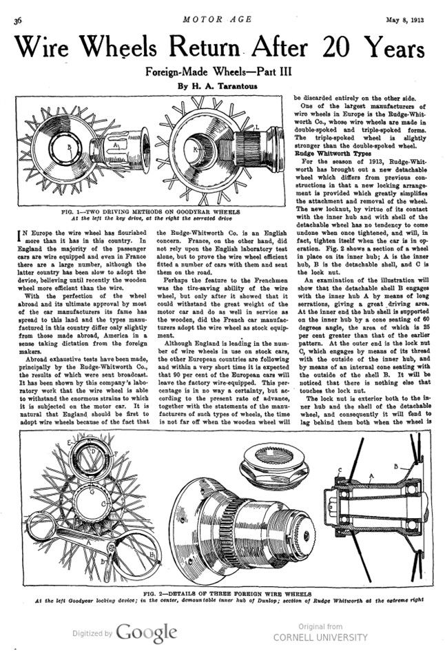
Two driving mechanisms are provided for the Goodyear detachable wire wheels: The key drive, is shown in Fig. 1. In this the keys, A, fit into suitably shaped grooves B in the wheel hub.
The serrated drive, Fig. 1, somewhat resembles the Rudge-Whitworth in that the serrations L on the axle hub, fit into similar ones at K inside of the wheel hub.
Goodyear Wire Wheels
In the type 10, the regular Goodyear practice is reversed by putting the driving studs on the brake drums, as shown in Fig. 2, and the holes in the shell. In addition to the driving studs the inner hub and wheel shell have a slight taper to relieve any possibility of stress on the driving pins.
The locking device is illustrated in Fig. 2. The method of attaching and detaching is simple. When the wrench is placed on the cap, the incline plane H on the wrench presses the plunger bridge and takes the secondary security lock G out of engagement. The turning of the wrench cam B, vertically disengages the primary lock D and plunger bridge E from the ratchet teeth on the hub. The cap is permanently retained on the wheel by a locking ring, and then is free to rotate and allow the wheel to be drawn on and off. This left-hand threaded locking ring, which is doubly secured on the cap, must first be removed if ever the cap requires to be taken off the wheel. Its function is to retain the cap on the wheel and to withdraw the wheel from the hub when the cap is rotated. The safety of the wheel in no way depends upon this ring. When the wheel has been placed on the hub and tightened by rotating the cap, the cam B is turned at right angles to the wrench and the plunger pin shoots up and draws the locks into engagement, and also draws the two locking pins F inside the cap. The wrench is then releasable.
Details of Riley Wheel
Three styles of wire wheels are made by Riley Ltd. These include, two detachable types; one with stud drive, and the other with a serrated driving hub; and a fixed wire wheel.
The stud drive wheel is shown in Fig. 4, dis-assembled from its hub, inner hub or axle. Permanently fitted to the inner hubs are the brake drums, bearings, speedometer, fittings, etc. The outer, or removable hub, which is built into the road wheel, is mounted upon the tapered seating of the inner hub, the projecting studs of which engage with the corresponding holes in the outer hub. These studs are tapered to a considerable degree to facilitate quick locating. It is claimed that the tapered seating takes practically the whole of the drive, and relieves the studs to a corresponding degree.
Each wheel is provided with a permanently attached hub cap, which is screw- threaded, to screw onto the thread of the inner hub. Self-contained in this hub cap are the automatic and positive locks, and also the withdrawal device. The outer shell has ratchet teeth cut on its end face, Fig. 3, which are adapted to be engaged by the plunger pawls of the hub cap. These pawls are pressed into engagement by large flat springs, and, one of the pawls is fitted with a swinging cover, which not only insures that its pawl is locked positively, but it further prevents the wrench being removed from the hub cap until one of the pawls is in positive engagement quite independent of spring action; the other pawl is in actual spring engagement.
Riley Serrated Drive
The Riley detachable wheel with the serrated drive, is a new type introduced at the request of some motor car makers desiring the tapered seating, but preferring invisible driving means. In this wheel, Fig. 3, the serrations take the form of a ring of gear teeth, formed solid in both inner and outer hubs.
Another type manufactured abroad is the Dunlop, a distinctive English make. It is made in triple-spoke form with a demountable hub, much the same as the Rudge-Whitworth. The demountable inner hub of the Dunlop here illustrated.
Photo captions.
FIG. 1 – TWO DRIVING METHODS ON GOODYEAR WHEELS
At the left the key drive, at the right the serrated drive
FIG. 2 – DETAILS OF THREE FOREIGN WIRE WHEELS
At the left Goodyear locking device; in the center, demountable inner hub of Dunlop; section of Rudge Whitworth at the extreme right
FIG. 3 – SPOKE ARRANGEMENT OF TWO TYPES AND RILEY DRIVE
Reading from left to right, Rudge-Whitworth, Riley double-spoke showing also serrated drive; stud-drive type of Riley wheel
FIG. 4 – TWO STUD DRIVES
Riley wheel and stud-drive hub at left; Goodyear stud-drive at right