


Bang Bang, Maxwells Silver Hammer! Not the Abbey Road song, but more than a century earlier already the Maywell silver hammer tried to blow a stroke in the 1906 Vanderbilt Cup Race. These Maxwell people most surely were not afraid of innovations; with all its accompanying risks. An opposite twelver, made of six 2-cylinder boxers with a total engine capacity of about 2.300 cu.in. or some 37 liters! More than 3 liters per cylinder. Must have been the largest engine in those days! The car appeared to be too heavy for the Vanderbilt rules, despite it was without a flywheel. Desparate measures to reduce weight were to no avail. Unfortunately, the car dissapeared from the scene sometime in 1907. But from a technical and innovative standpoint; an interesting beauty! The second part deals with the air-cooled Frayer-Miller machine; another innovator.
Text and jpegs by courtesy of hathitrust.org www.hathitrust.org, compiled by motorracinghistory.com
MOTOR AGE Vol. X, No. 10 Chicago, September 6, 1906
Automobile Development – Maxwell 12 Cylinder Vanderbilt Cup Racer
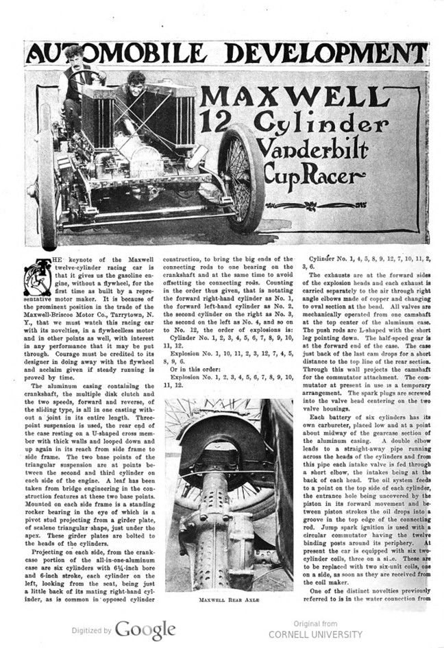
THE keynote of the Maxwell twelve-cylinder racing car is that it gives us the gasoline engine, without a flywheel, for the first time as built by a representative motor maker. It is because of the prominent position in the trade of the Maxwell-Briscoe Motor Co., Tarrytown, N. Y., that we must watch this racing car with its novelties, in a flywheel-less motor and in other points as well, with interest in any performance that it may be put through. Courage must be credited to its designer in doing away with the flywheel and acclaim given if steady running is proved by time.
The aluminum casing containing the crankshaft, the multiple disk clutch and the two speeds, forward and reverse, of the sliding type, is all in one casting without a joint in its entire length. Three-point suspension is used, the rear end of the case resting on a U-shaped cross member with thick walls and looped down and up again in its reach from side frame to side frame. The two base points of the triangular suspension are at points between the second and third cylinder on each side of the engine. A leaf has been taken from bridge engineering in the construction features at these two base points. Mounted on each side frame is a standing rocker bearing in the eye of which is a pivot stud projecting from a girder plate, of scalene triangular shape, just under the apex. These girder plates are bolted to the heads of the cylinders.
Projecting on each side, from the crank-case portion of the all-in-one-aluminum case are six cylinders with 6¼-inch bore and 6-inch stroke, each cylinder on the left, looking from the seat, being just a little back of its mating right-hand cylinder, as is common in opposed cylinder construction, to bring the big ends of the connecting rods to one bearing on the crankshaft and at the same time to avoid offsetting the connecting rods. Counting in the order thus given, that is notating the forward right-hand cylinder as No. 1, the forward left-hand cylinder as No. 2, the second cylinder on the right as No. 3, the second on the left as No. 4, and so on to No. 12, the order of explosions is:
Cylinder No. 1, 2, 3, 4, 5, 6, 7, 8, 9, 10, 11, 12.
Explosion No. 1, 10, 11, 2, 3, 12, 7, 4, 5, 8, 9, 6. 7
Or in this order:
Explosion No. 1, 2, 3, 4, 5, 6, 7, 8, 9, 10, 11, 12.
Cylinder No. 1, 4, 5, 8, 9, 12, 7, 10, 11, 2, 3, 6.
The exhausts are at the forward sides of the explosion heads, and each exhaust is carried separately to the air through right angle elbows made of copper and changing to oval section at the bend. All valves are mechanically operated from one camshaft at the top center of the aluminum case. The push rods are L-shaped with the short leg pointing down. The half-speed gear is at the forward end of the case. The case just back of the last cam drops for a short distance to the top line of the rear section. Through this wall projects the camshaft for the commutator attachment. The commutator at present in use is a temporary arrangement. The spark plugs are screwed into the valve head centering on the two valve housings.
Each battery of six cylinders has its own carbureter, placed low and at a point about midway of the gearcase section of the aluminum casing. A double elbow leads to a straight-away pipe running across the heads of the cylinders and from this pipe each intake valve is fed through a short elbow, the intakes being at the back of each head. The oil system feeds to a point on the top side of each cylinder, the entrance hole being uncovered by the piston in its forward movement and between piston strokes the oil drops into a groove in the top edge of the connecting rod. Jump spark ignition is used with a circular commutator having the twelve binding posts around its periphery. At present the car is equipped with six two- cylinder coils, three on a sine. These are to be replaced with two six-unit coils, one on a side, as soon as they are received from the coil maker.
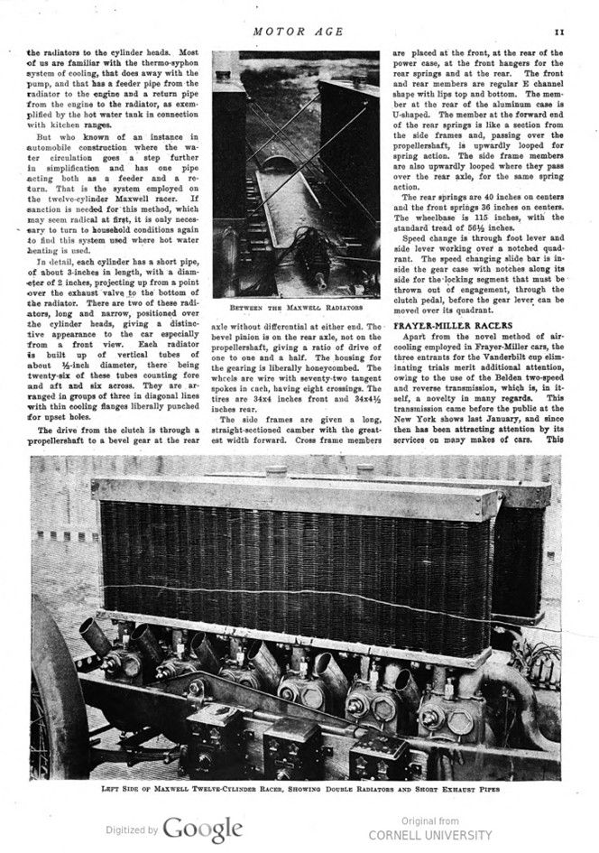
One of the distinct novelties previously referred to is in the water connection from the radiators to the cylinder heads. Most of us are familiar with the thermo-syphon system of cooling, that does away with the pump, and that has a feeder pipe from the radiator to the engine and a return pipe from the engine to the radiator, as exemplified by the hot water tank in connection with kitchen ranges.
But who knows of an instance in automobile construction where the water circulation goes a step further in simplification and has one pipe acting both as a feeder and a return. That is the system employed on the twelve-cylinder Maxwell racer. If sanction is needed for this method, which may seem radical at first, it is only necessary to turn to household conditions again to find this system used where hot water heating is used.
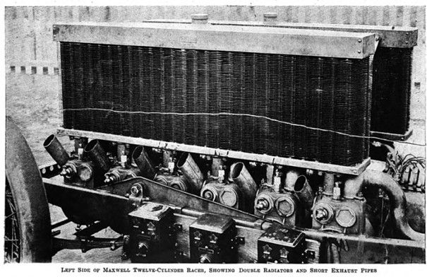
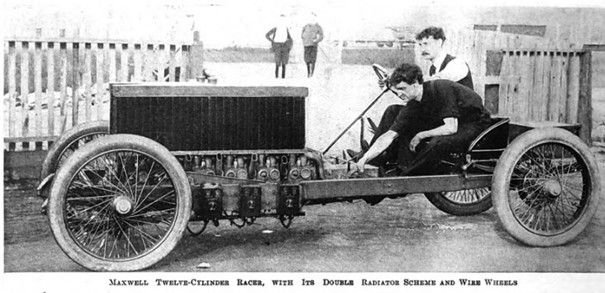
In detail, each cylinder has a short pipe of about 3-inches in length, with a diameter of 2 inches, projecting up from a point over the exhaust valve to the bottom of the radiator. There are two of these radiators, long and narrow, positioned over the cylinder heads, giving a distinctive appearance to the car especially from a front view. Each radiator is built up of vertical tubes of about ½-inch diameter, there being twenty-six of these tubes counting fore and aft and six across. They are arranged in groups of three in diagonal lines with thin cooling flanges liberally punched for upset holes.
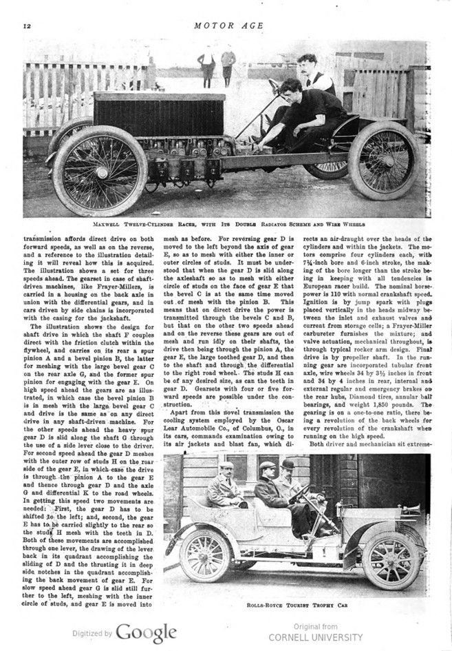
The drive from the clutch is through a propeller-shaft to a bevel gear at the rear axle without differential at either end. The bevel pinion is on the rear axle, not on the propeller-shaft, giving a ratio of drive of one to one and a half. The housing for the gearing is liberally honeycombed. The wheels are wire with seventy-two tangent spokes in cache, having eight crossings. The tires are 34×4 inches front and 34×4½ inches rear.
The side frames are given a long, straight-sectioned camber with the greatest width forward. Cross frame members are placed at the front, at the rear of the power case, at the front hangers for the rear springs and at the rear. The front and rear members are regular E channel shape with lips top and bottom. The member at the rear of the aluminum case is U-shaped. The member at the forward end of the rear springs is like a section from the side frames and, passing over the propeller-shaft, is upwardly looped for spring action. The side frame members are also upwardly looped where they pass over the rear axle, for the same spring action.
The rear springs are 40 inches on centers and the front springs 36 inches on centers. The wheelbase is 115 inches, with the standard tread of 56½ inches.
Speed change is through foot lever and side lever working over a notched quadrant. The speed changing slide bar is inside the gear case with notches along its side for the locking segment that must be thrown out of engagement, through the clutch pedal, before the gear lever can be moved over its quadrant.
FRAYER-MILLER RACERS
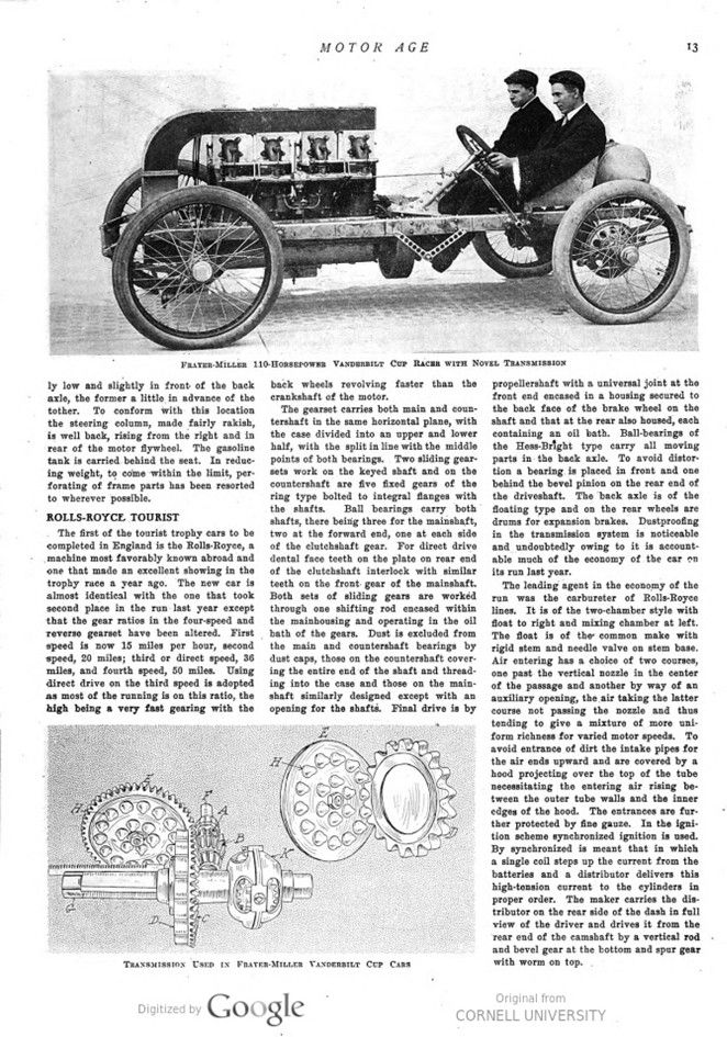
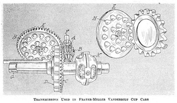
Apart from the novel method of air-cooling employed in Frayer-Miller cars, the three entrants for the Vanderbilt cup eliminating trials merit additional attention, owing to the use of the Belden two-speed and reverse transmission, which is, in itself, a novelty in many regards. This transmission came before the public at the New York shows last January, and since then has been attracting attention by its services on many makes of cars. This transmission affords direct drive on both forward speeds, as well as on the reverse, and a reference to the illustration detailing it will reveal how this is acquired.
The illustration shows a set for three speeds ahead. The gearset in case of shaft-driven machines, like Frayer-Millers, is carried in a housing on the back axle in union with the differential gears, and in cars driven by side chains is incorporated with the casing for the jackshaft. The illustration shows the design for shaft drive in which the shaft F couples direct with the friction clutch within the flywheel, and carries on its rear a spur pinion A and a bevel pinion B, the latter for meshing with the large bevel gear C on the rear axle G, and the former spur pinion for engaging with the gear E. On high speed ahead the gears are as illustrated, in which case the bevel pinion B is in mesh with the large bevel gear C and drive is the same as“ on any direct drive in any shaft-driven machine. For the other speeds ahead the heavy spur gear D is slid along the shaft G through the use of a side lever close to the driver. For second speed ahead the gear D meshes with the outer row of studs H on the rear side of the gear E, in which case the drive is through the pinion A to the gear E and thence through gear D and the axle G and differential K to the road wheels. In getting this speed two movements are needed: First, the gear D has to be shifted to the left; and, second, the gear E has to be carried slightly to the rear so the studs H mesh with the teeth in D. Both of these movements are accomplished through one lever, the drawing of the lever, back in its quadrant, accomplishing the sliding of D and the thrusting it in deep side, notches in the quadrant accomplishing the back movement of gear E. For slow speed ahead gear G is slid still further to the left, meshing with the inner circle of studs, and gear E is moved into mesh as before. For reversing gear D is moved to the left beyond the axis of gear E, so as to mesh with either the inner or outer circles of studs. It must be understood that when the gear D is slid along the axle-shaft so as to mesh with either circle of studs on the face of gear E that the bevel C is at the same time moved out of mesh with the pinion B. This means that on direct drive the power is transmitted through the bevels C and B, but that on the other two speeds ahead and on the reverse these gears are out of mesh and run idly on their shafts, the drive then being through the pinion A, the gear E, the large toothed gear D, and then to the shaft and through the differential to the right road wheel. The studs H can be of any desired size, as can the teeth in gear D. Gearsets with four or five forward speeds are possible under the construction.
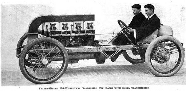
Apart from this novel transmission, the cooling system employed by the Oscar Lear Automobile Co., of Columbus, O., in its cars, commands examination owing to its air jackets and blast fan, which directs an air-draught over the heads of the cylinders and within the jackets. The motors comprise four cylinders each, with 74-inch bore and 6-inch stroke, the making of the bore longer than the stroke being in keeping with all tendencies in European racer build. The nominal horsepower is 110 with normal crankshaft speed. Ignition is by jump spark with plugs. placed vertically in the heads midway between the inlet and exhaust valves and current from storage cells; a Frayer-Miller carbureter furnishes the mixture; and valve actuation, mechanical throughout, is through typical rocker arm design. Finał drive is by propeller shaft. In the running gear are incorporated tubular front axle, wire wheels 34 by 3½ inches in front and 34 by 4 inches in rear, internal and external regular and emergency brakes on the rear hubs, Diamond tires, annular ball bearings, and weight 1,850 pounds. The gearing is on a one-to-one ratio, there being a revolution of the back wheels for every revolution of the crankshaft when running on the high speed.
Both driver and mechanician sit extremely low and slightly in front of the back axle, the former a little in advance of the tother. To conform with this location the steering column, made fairly rakish, is well back, rising from the right and in rear of the motor flywheel. The gasoline tank is carried behind the seat. In reducing weight, to come within the limit, perforating of frame parts has been resorted to wherever possible.
Photos.
Page 10. MAXWELL REAR AXLE
Page 11. BETWEEN THE MAXWELL RADIATORS – LEFT SIDE OF MAXWELL TWELVE-CYLINDER RACER, SHOWING DOUBLE RADIATORS AND SHORT EXHAUST PIPES
Page 12. MAXWELL TWELVE-CYLINDER RACER, WITH ITS DOUBLE RADIATOR SCHEME AND WIRE WHEELS – ROLLS-ROYCE TOURIST TROPHY CAR
Page 13. FRAYER-MILLER 110-HORSEPOWER VANDERBILT CUP RACER WITH NOVEL TRANSMISSION – TRANSMISSION USED IN FRAYER-MILLER VANDERBILT CUP CARS