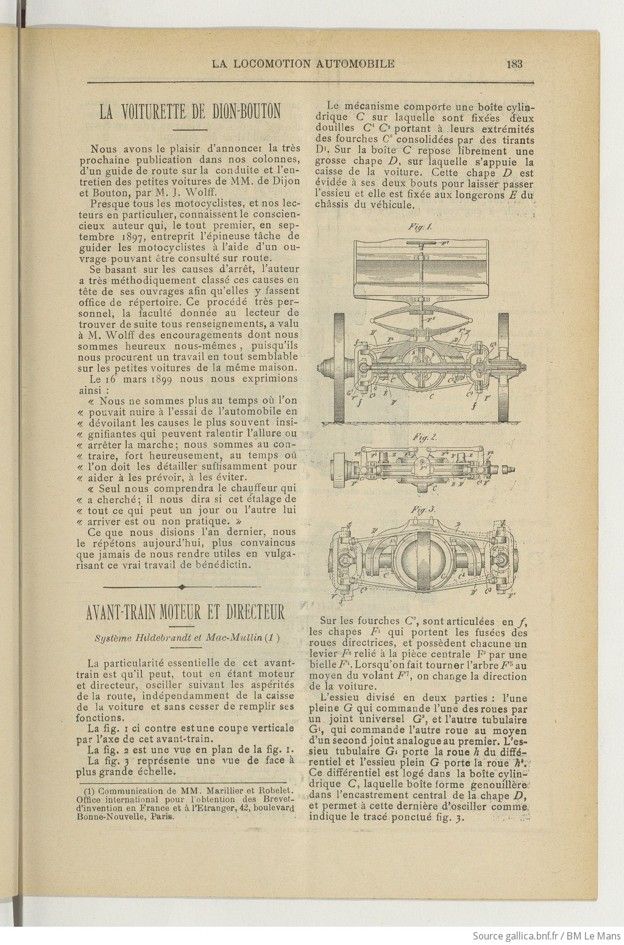
This front-wheel drive system of 1900 has a front-end unit (French: avant-train) which incorporates driving and steering in one. The driving function is performed by differential gears, similar to a normal differential. Both driving axles left-right side, are attached to the wheels by means of universal joints. The steering function is realized by normal steering rods, that are actuated by the vertical steering wheel. The only problem I have, is that I cant distinguish how the actual driving rotation of the middle differential is realized. I only can imagine a pinion-crownwheel combination of which the crownwheel is housed in the casing C. (Translation included)
Avec l’authorisation du Bibliothèque national francais, gallica.bnf.fr.
Text et photos compilé par motorracingistory.com. (Translation by DeepL.com)
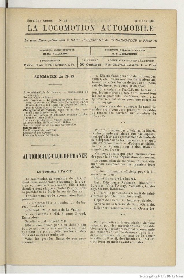
La Locomotion Automobile, 7e Année, No. 12, 22 mars 1900, page 183
AVANT-TRAIN MOTEUR ET DIRECTEUR
Système Hildebrandt et Mac-Mullin (1)
La particularité essentielle de cet avant-train est qu’il peut, tout en étant moteur et directeur, osciller suivant les aspérités de la route, indépendamment de la caisse de la voiture et sans cesser de remplir ses fonctions.
La fig. 1 ci-contre est une coupe verticale par Taxe de cet avant-train.
La fig. 2 est une vue en plan de la fig. 1.
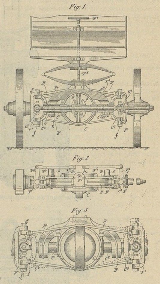
La fig. 3 représente une vue de face à plus grande échelle.
Le mécanisme comporte une boîte cylindrique C sur laquelle sont fixées deux douilles C‘ C2 portant à leurs extrémités des fourches C3 consolidées par des tirants D1. Sur la boîte C repose librement une grosse chape Z), sur laquelle s’appuie la caisse de la voiture. Cette chape D est évidée à ses deux bouts pour laisser passer l’essieu et elle est fixée aux longerons E du châssis du véhicule.
Sur les fourches C3, sont articulées en fy les chapes F1 qui portent les fusées des roues directrices, et possèdent chacune un levier F* relié à la pièce centrale F3 par une bielle F*. Lorsqu’on fait tourner l’arbre F3 au moyen du volant F7, on change la direction de la voiture.
L’essieu divisé en deux parties : Tune pleine G qui commande Tune des roues par un joint universel G’, et l’autre tubulaire Gi, qui commande l’autre roue au moyen d’un second joint analogue au premier. L’essieu tubulaire Gi porte la roue h du différentiel et l’essieu plein G porte la roue hi. Ce différentiel est logé dans la boîte cylindrique C, laquelle boîte forme genouillère-dans l’encastrement central de la chape D, et permet à cette dernière d’osciller comme indique le tracé ponctué fig. 3.
(1) Communication de MM. Marillier et Eobelet. Office international pour l’obtention des Brevet-d’invention en France et à l’Etranger, 42, boulevard Bonne-Nouvelle, Paris.
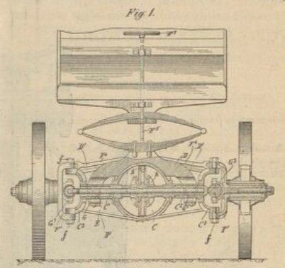
Fig. 1 opposite is a vertical cross-section by Taxe of this front end.
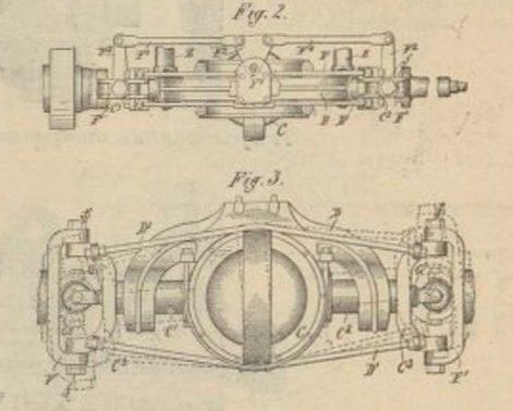
Fig. 2 is a plan view of Fig. 1.
La fig. 3 représente une vue de face à plus grande échelle.
Fig. 3 shows a front view on a larger scale.
—>> fig. 1 – fig. 2 – fig. 3 —>>
Translation by DeepL.com
FRONT END DRIVE AND STEERING UNIT
Hildebrandt and Mac-Mullin System (1) [possibly: McMullin]
The key feature of this front end is that, while serving as both a drive and steering mechanism, it can oscillate in response to road irregularities, independently of the car body and without ceasing to perform its functions.
Fig. 1 opposite is a vertical cross-section by Taxe of this front end.
Fig. 2 is a plan view of Fig. 1.
Fig. 3 shows a front view on a larger scale.
The mechanism comprises a cylindrical housing C to which two sleeves C’ and C2 are attached, each bearing at its ends a fork C3 reinforced by tie rods D1. A large yoke (Z) rests freely on the housing C, upon which the vehicle body rests. This yoke (D) is hollowed out at both ends to allow the axle to pass through and is secured to the side members (E) of the vehicle chassis.
Articulated at point fy on the forks C3 are the yoke arms F1, which carry the steering knuckles of the steering wheels and each have a lever F* connected to the central component F3 by a connecting rod F*. When the shaft F3 is rotated using the steering wheel F7, the direction of the car is changed.
The axle is divided into two parts: a solid section G, which drives one of the wheels via a universal joint G’, and a tubular section Gi, which drives the other wheel by means of a second joint similar to the first. The tubular axle Gi carries the wheel h of the differential, and the solid axle G carries the wheel hi. This differential is housed in the cylindrical housing C, which forms a toggle joint within the central recess of the yoke D and allows the yoke to oscillate as indicated by the dotted line in Fig. 3.
(1) Communication from Messrs. Marillier and Eobelet. International Office for the Granting of Patents in France and Abroad, 42 Boulevard Bonne-Nouvelle, Paris.