Text and jpegs by courtesy of hathitrust.org www.hathitrust.org, compiled by motorracinghistory.com
Motor Age, Vol. LIII, 53, No. 18, May 3, 1928
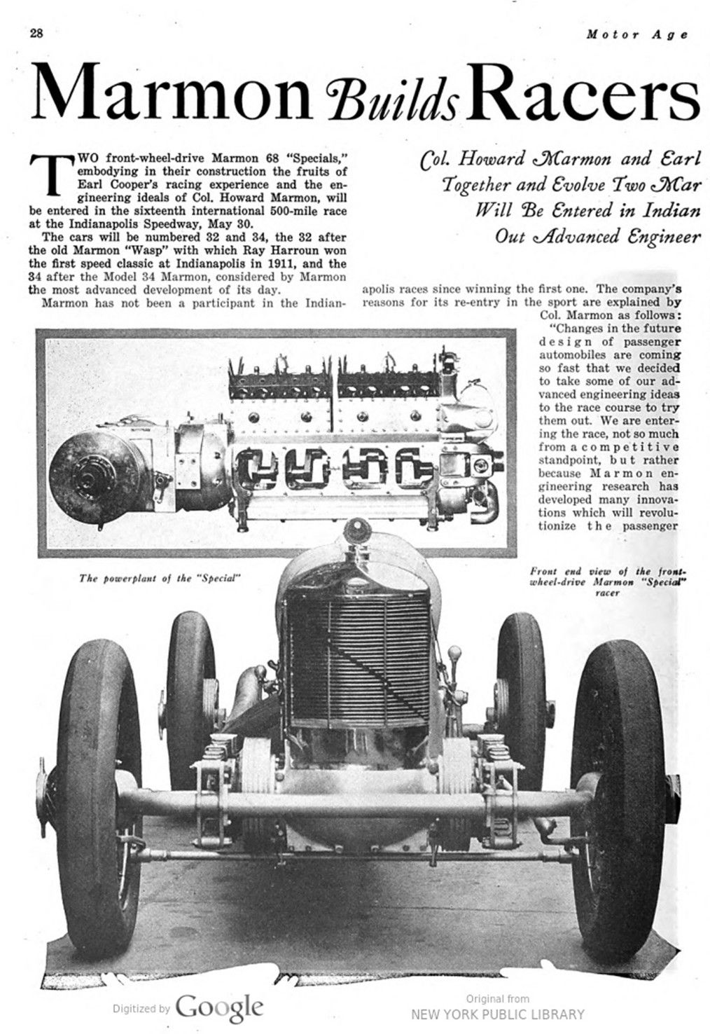
Marmon Builds Racers for Tests
Col. Howard Marmon and Earl Cooper Put Their Heads Together and Evolve Two Marmon 68 „Specials“ Which Will Be Entered in Indianapolis Classic to Try Out Advanced Engineering Ideas
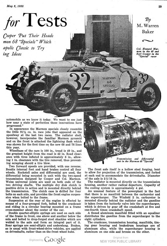
By M. Warren Baker
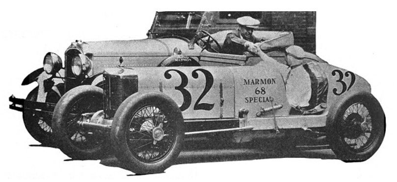
TWO front-wheel-drive Marmon 68 „Specials,“ embodying in their construction the fruits of Earl Cooper’s racing experience and the engineering ideals of Col. Howard Marmon, will be entered in the sixteenth international 500-mile race at the Indianapolis Speedway, May 30.
The cars will be numbered 32 and 34, the 32 after the old Marmon „Wasp“ with which Ray Harroun won the first speed classic at Indianapolis in 1911, and the 34 after the Model 34 Marmon, considered by Marmon the most advanced development of its day.
Marmon has not been a participant in the Indianapolis races since winning the first one. The company’s reasons for its re-entry in the sport are explained by Col. Marmon as follows:
„Changes in the future design of passenger automobiles are coming so fast that we decided to take some of our advanced engineering ideas to the racecourse to try them out. We are entering the race, not so much from a competitive standpoint, but rather because Marmon engineering research has developed many innovations which will revolutionize the passenger automobile as we know it today. We want to see just how near a state of perfection these innovations have progressed.“
In appearance the Marmon specials closely resemble the little 9½ cu. in. race jobs that appeared on the speedway at the last two races. The radiator shell, however, incorporates the familiar Marmon pyramid and on the front is attached the lightning flash which was shown for the first time on the new 68 and 78 lines this year.
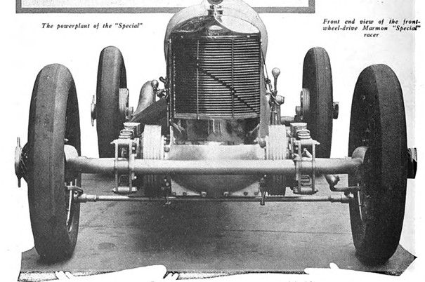
Wheelbase of the cars is 100 in., tread is 49 in., and the greatest height from the road is 42 in. Road clearance with tires inflated is approximately 6 in., allowing 1 in. clearance with the tire removed, thus preventing scraping should a tire blow.
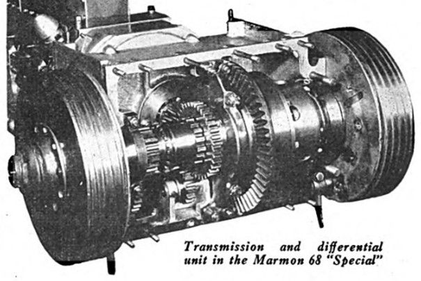
Two forward speeds are provided, with one reverse. Bendix internal foot and hand brakes control all four wheels. Ruckstell axles and differential are used, the differential being mounted in unit with the two-speed transmission designed by Cooper and Col. Marmon. Weiss universal joints are used on both ends of the two driving shafts. The multiple dry disk clutch is positive drive in action and is mounted directly behind the transmission. The clutch case is drilled for four bolts on each side and provides the front engine suspension when bolted to the frame.
Suspension at the rear of the engine is effected by means of a four-pronged fork, bolted to the crankcase and riding in a circular bearing mounted on a frame cross-member about the center of the car.
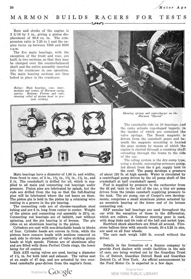
Double quarter-elliptic springs are used on each side of the frame in front, one above and another below the axle and bolted to drop-forged steel shackles which are welded to the axle and form an integral part of it. Rear springs are semi-elliptic and underslung. Brakes, as is usual with front-wheel-drive vehicles, are applied on driveshafts, rather than on the front wheel hubs.
The front axle itself is a hollow steel forging, bent to allow for projection of the transmission, and forked at each end to accommodate the driveshafts. Diameter of the axle is 23/16 in.
The radiator is mounted directly on the transmission housing, another rather radical departure. Capacity of the cooling system is approximately 4 gal.
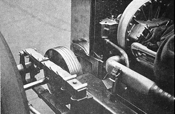
An unusual feature of the powerplant is the fact that there is no manifold between the carburetor and the supercharger. The Winfield 2 in. carburetor is mounted directly behind the radiator and the gasoline is taken from the butterfly valve into the supercharger, which is driven by gear off the crankshaft at five and one-fourth times crankshaft speed.
A finned aluminum manifold fitted with an equalizer distributes the gasoline from the supercharger to the eight cylinders.
The crankcase, transmission housing, manifolds, timing gear housing and brake drum housings are of aluminum alloy, while the supercharger housing is aluminum on one side and bronze on the other.
Bore and stroke of the engine is 2 3/16 by 3 in., giving a piston displacement of 90.8 cu. in. The compression ratio is 7.25 to 1 and the engine turns up between 7500 and 8000 r.p.m.
The five main bearings, with the exception of the front and rear, are built in two sections, so that they may be clamped over the counterbalanced shaft and the entire assembly inserted into the crankcase in one operation. The main bearing sections are then bolted in place in the crankcase.
Main bearings have a diameter of 1.86 in. and widths, from front to rear, of 2 in., 1 ¼ in., 1¾ in., 1¼ in., and 2 in. The crankshaft is drilled for oil, which is supplied to all main and connecting rod bearings under pressure. Piston pins are lubricated by splash, but the rods are drilled from the top so that the full-floating pins will be lubricated where the rod bears on them. The piston pin is held in the piston by a retaining wire resting in a groove in the pin bearing.
The connecting rods are of chrome-vanadium steel tubing and are 6 in. long from center to center. Weight of the piston and connecting rod assembly is 23½ oz. Connecting rod bearings are of babbitt, cast without spinning, and the pin bearing is of bronze. The pin rides on an aluminum bearing in the piston.
Cylinders are cast with non-detachable heads in blocks of four. Cylinder heads are convex in form, while the pistons have concave heads with sections removed on each side to obviate possibility of valve striking piston heads at high speeds. Pistons are of aluminum alloy and are fitted with three Perfect Circle rings, the lower being for oil control.
Rich AES racing valves are used, having a diameter of 114 in. for both inlet and exhaust. The valves seat at an angle of 47 deg. and are actuated by two overhead camshafts gear-driven from the engine’s front.
The camshafts ride on 10 bearings, and the cams actuate cup-shaped tappets, in the insides of which are contained the valve springs. The Bosch magneto is driven from the camshaft gears and beneath the magneto mounting is located the gear system by means of which the engine is started through a cranking shaft extending through the frame to the side of the car.
The oiling system is the dry-sump type, using a double, scavenging-pressure pump, fed direct from the 8 gal. supply tank in the cowl. The pump develops a pressure of about 120 lb. at high speeds. Water is circulated by a centrifugal pump driven by the oil pump shaft of the crankshaft at half crankshaft speed.
Fuel is supplied by pressure to the carburetor from the 42 gal. tank in the tail of the car, a tiny air pump driven from the intake camshaft supplying pressure to the tank. The air pump, one of Cooper’s own developments, comprises a small aluminum piston actuated by an eccentric bearing at the lower end of its bronze connecting rod.
SKF annular ball bearings are used throughout the car with the exception of those in the differential, which are rollers. A Gemmer steering gear is used, with drag links and tie rods of the ball and socket type. Hartford shock absorbers are fitted all around. Firestone balloon tires with smooth treads, 20 x 5.25 in size, are used on all four wheels. The cars each weigh 1450 lb. overall without the driver.
Photos.
Page 28.
The powerplant of the „Special“
Front end view of the front- wheel-drive Marmon „Special“ racer
Page 29.
Col. Howard Marmon in the 68 and Earl Cooper in the „Special“ racer
Transmission and differential unit in the Marmon 68 „Special“
Page 30.
Below: Main bearings, rear, intermediate and center, of Marmon racing entries.
Bottom: Pistons and rods, showing relief of piston head to pre- vent striking
Showing springs and supercharger on the Marmon „Special“