


This article was published in May 1902! Here, the well-known French technicalist-journalist and writer of several books on automobiles, Louis Baudry de Sainier describes the 1902 Roulleau & Pilat sans-chevaux with front-wheel drive. Mind You; I believe that this is one of the two first continental front-wheel driven cars. The Austrian Gräf & Stift was the other one. This article consists of two parts; the first one dealing with the general issues of those days front versus rear wheel drive. The second part describes the transmission + differential, as well as the shaft joints. These look very much like the later patented Tracta constant-velocity joint. Means, this car applied already cv-joints, about 20 years before a similar joint was used. I was baffled and positively surprised, finding these two articles, dating back to 1902.


With authorisation of Conservatoire numérique des Arts et Métiers (Cnum) – https://cnum.cnam.fr
Text and photos compiled by motorracinghistory.com
La Vie Automobile Volume 2. — N° 34. – Saturday May 24, 1902.
The Roulleau and Pilât Car (Car with front-wheel drive) – I
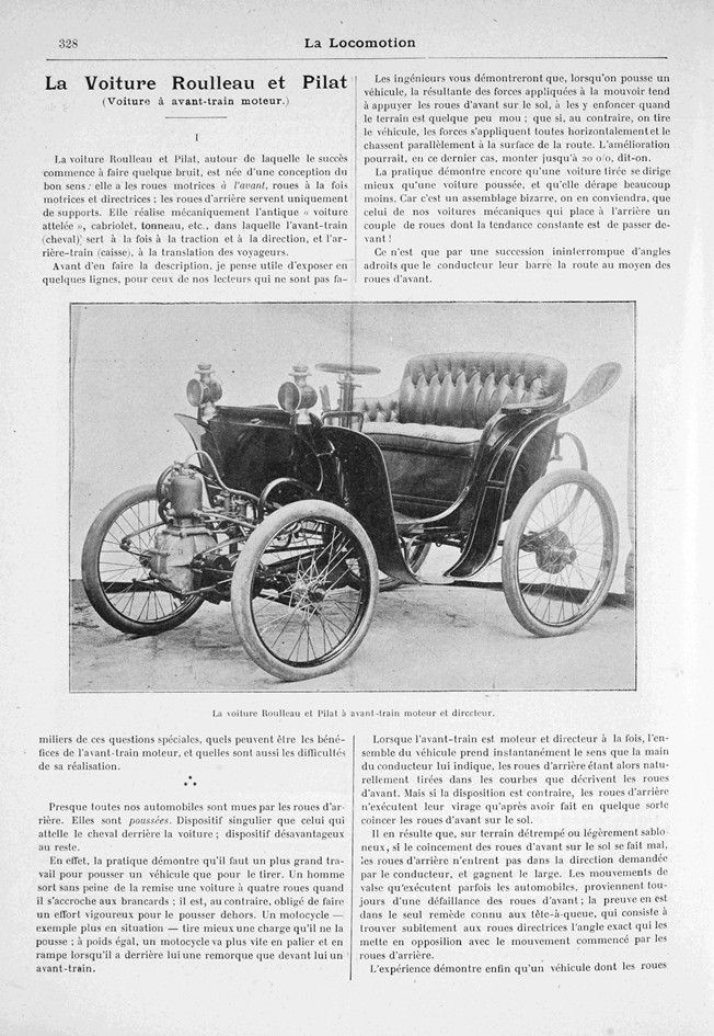
The Roulleau et Pilât vehicle, which is beginning to attract attention due to its success, was born from a common-sense design: it has drive wheels at the front, which are both drive and steering wheels; the rear wheels are used solely for support. It mechanically replicates the ancient “horse-drawn carriage,” cabriolet, tonneau, etc., in which the front end (horse) is used for both traction and steering, and the rear end (body) is used to transport passengers.
Before describing it, I think it would be useful to explain in a few lines, for those of our readers who are not familiar with these specialized issues, what the benefits of front-wheel drive can be, and what the difficulties of implementing it are.
* * *
Almost all our automobiles are driven by the rear wheels. They are pushed. The device that harnesses the horse behind the car is a singular one; it is also a disadvantageous device.
In fact, practice shows that it takes more effort to push a vehicle than to pull it. A man can easily pull a four-wheeled car out of the shed by holding on to the shafts; but he has to make a vigorous effort to push it out. A motorcycle — a more relevant example — pulls a load better than it pushes it; with equal weight, a motorcycle goes faster on level ground and uphill when it has a trailer behind it than when it has a front axle in front of it.
Engineers will show you that when a vehicle is pushed, the resultant of the forces applied to move it tends to press the front wheels into the ground, sinking them into it when the ground is somewhat soft; that if, on the contrary, the vehicle is pulled, the forces are all applied horizontally and drive it parallel to the surface of the road. In the latter case, the improvement could be as much as 20%, it is said.
Practice also shows that a pulled vehicle steers better than a pushed vehicle and skids much less. For it is a strange combination, we must agree, that of our mechanical vehicles, which place at the rear a pair of wheels whose constant tendency is to go ahead!
It is only through a continuous succession of skillful angles that the driver blocks their path with the front wheels.
When the front axle is both the engine and the steering mechanism, the entire vehicle instantly turns in the direction indicated by the driver’s hand, with the rear wheels naturally following the curves described by the front wheels. But if the layout is reversed, the rear wheels only turn after the front wheels have become stuck to the ground, so to speak.
As a result, on wet or slightly sandy ground, if the front wheels are not properly stuck to the ground, the rear wheels do not turn in the direction requested by the driver and veer off course. The waltzing movements that cars sometimes perform are always caused by a failure of the front wheels; the proof of this lies in the only known remedy for spinning out, which consists of suddenly finding the exact angle for the steering wheels that opposes the movement initiated by the rear wheels.
Experience shows that a vehicle with rear-wheel drive cannot turn its front wheels beyond a slight angle of about 25° without failing to start, since the front axle will lock against the rear axle, and without also risking tipping over while driving. It can therefore only pull out of a line of cars if it is a few meters away from the one in front of it; it can only turn on a narrow road by moving forward and backward in succession. The front drive axle, on the other hand, can start at almost a right angle to the rest of the vehicle; it can turn extremely sharply and safely. It is well known that, when going around a curve, a train pushed by a locomotive derails very easily, whereas it follows the locomotive unerringly when it pulls it.
In short, the superiority of the front horse over the rear horse seems indisputable, theoretically.
In practical terms — that is, from the point of view of ease of handling and maintenance — the front-engine layout is even less debatable.
It is, in fact, an almost perfect simplification, as it completely eliminates the need for components hidden under the body. The engine, with its water, fuel, and battery attachments, etc., transmits motion to the drive wheels without chains or cardan shafts, via gears located immediately adjacent to it. As a result, the entire mechanism is housed in the front, under a hood and in a general compartment that protects it from water, dust, and mud, in a space limited to about a quarter of a cubic meter.
Accessibility to every component is therefore excellent, to such an extent that the engine unit, with its multiple components and even all its tanks, can form a single block that slides onto the front extensions of the chassis, is secured there with four bolts, and can therefore be placed on one body or removed from another without ever touching the car itself.
It is easy to see that such a dense grouping of components has the indirect — but very important — effect of making it possible to build a front-engine car more cheaply than a rear-engine car. The length of the water pipes, exhaust pipes, fuel lines, wires, transmissions, and movement controls is considerably reduced; assembly is extremely simple and never requires work in a pit; the chassis, which now only supports passengers at the rear, does not need the reinforcements and struts that it requires when it supports high-powered drive shafts, etc.
It therefore seems that it is through the front axle that we will soon achieve the popular automobile, popular because of its low price and the simplicity of its components.
* * *
However, there are both theoretical and practical objections to the front-wheel drive.
The first is the poor grip that the front wheels have on the ground when they are not carrying a heavy load. This lack of grip is not a problem when the front wheels are only used for steering; however, it becomes a major issue when they are also used for propulsion. In some cases, a lack of traction could completely prevent the vehicle from moving forward; normally, it would reduce its speed and cause extremely rapid tire wear.
This disadvantage can be remedied by balancing the weight of the loaded car with that of the engine and its accessories, with the engine and its accessories providing most of the traction applied to the wheels. It would also be advisable to move the rear axle as far back as possible towards the rear of the body so that its weight and that of its passengers never tend to counterbalance that of the front axle, but instead contribute to its grip on the ground.
In two-seater cars, as passengers are necessarily located within the rectangle formed by the sides of the chassis and the axles, there is no risk of skidding. In multi-seat cars, it will be necessary to ensure that the rear seats are not too far outside the axle and do not act as a counterweight; the front seats could even be placed above the engine itself, so that the load on this axle is as great as possible and the rear seats do not balance it in any way.
The second objection to the front drive axle is the difficulty of its installation.
The difficulty lies in making this front axle both drive and steering.

One might think, a priori, that the problem could be solved by dividing the roles of the two axles of the car, as they are currently, but reversing them: the drive wheels would be at the front and the steering wheels at the rear. However, apart from losing many of the advantages of the steering front axle (very short turning radius, etc.), vehicles, both bicycles and automobiles, that have been built on this idea have proven that, at speeds exceeding approximately 20 kilometers per hour, there is no steering more imprecise than that provided by the rear axle. At 40 kilometers per hour, such a vehicle would be a death trap.
Researchers are therefore obliged to stick to the complicated problem of the front axle being both the drive and the steering mechanism.
The first solution that comes to mind is this: a single drive wheel at the front, making a tricycle. However, if the vehicle has only one wheel at the front, the entire mechanism must necessarily be installed on it.
The bulk becomes such and the difficulty of steering such a heavy wheel proves so considerable that it becomes impossible. I will not mention the justified disapproval of three-wheeled vehicles with two seats side by side.
It is therefore necessary to keep two parallel wheels at the front. If the vehicle has two wheels at the front, we can try to mount them on a rigid axle with a central pivot. By means of a combination of simple gears, we can use the pivot to transmit the movement of the engine to both wheels, regardless of the position of the axle in relation to the chassis. However, the steering system with front wheels mounted on a pivot axle (as in horse-drawn carriages) has fierce detractors who do not seem to be wrong. These critics say that at slightly higher speeds, this type of steering is dangerous because, in order to turn even slightly to the right or left, the axle must be turned at a wide angle, and in order to make a tight turn, one is forced to bring one of the wheels right up under the body, thereby considerably reducing the car’s wheelbase. Finally, this system has the disadvantage of only being applicable to fairly high cars, since space must be left under the body for the wheels to pass through.
The problem is becoming more acute.
We are forced to look for a front axle that is both driven and steered, consisting of two wheels mounted on the split axle commonly found in automobiles!
These data seem to be mutually exclusive. At first glance, it seems impossible that a rotating shaft could transmit its movement to two wheels mounted at each end, when these wheels, in order to steer the vehicle, will almost never be in line with it, but will instead constantly form angles of constantly changing values with it!
* * *
In the next issue, we will see how, by extremely simple means—a well-designed cardan joint—Messrs. Rouleau and Pilât, whose simple cars we are showing today, found the solution to this last problem.
Let us also mention that Messrs. Roulleau and Pilât, inspired as they are, equip all their cars with Dion-Bouton engines. Our study will therefore focus solely on the ingenious way in which they transmit power to the front wheels. (To be continued). L. Baudry de Saunier.

The Roulleau and Pilât Car (Car with Front-Wheel Drive) – II (Continued)
The success achieved by Messrs. Roulleau and Pilât in the construction of their front end, which serves as both engine and tractor, is mainly due to the joint nut they designed to allow the drive shafts to bend to the movements of the car’s suspension, and especially to the requirements of the continuous changes in direction made by the drive wheels under the impulse of the hand that steers them.
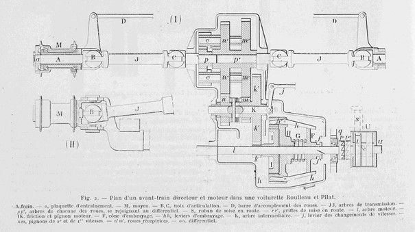
Their nut, which can be clearly seen in B and G (fig. 1), consists of two small forks perpendicular to each other, mounted on a ball with two grooves in which they can move. If we refer to figure 2, we can see (on the left) that shaft J ends in a fork fitted into ball B, while spindle A ends in another fork, also fitted into ball B, but perpendicular to the first. The plan view of this joint and its elevation view (below) clearly show the special features of this coupling.
The flexibility of this joint is such that the wheel can form a 45° angle with the chassis without the shaft to stop from rotating, and without any vibration or irregularity occurring.
With this convenient nut in their possession, Messrs. Roulleau and Pilât had almost won the game. All they needed was a little ingenuity to put a suitable front end on wheels. However, as we shall see, they were not lacking in ingenuity, and the details of their construction are most curious.
Let us assume that the motor is connected to the left end of shaft l (fig. 2). A fixed part H is keyed onto it, on which the clutch spring G rests to push back the movable cone E on the shaft.
On the other hand, the intermediate gear k‘ remains constantly engaged with a pinion k that is integral with a drum I that rotates freely on the motor shaft. We understand that if we can make this drum I integral with the motor shaft, we will immediately activate the gear k‘ and, through it, the entire transmission to the wheels.
However, I is adjacent to II, which is integral with the shaft, and since H has four levers h (only two are visible in the diagram), it will suffice for these four levers to pinch I firmly to make it integral with H, i.e., with the drive shaft.
In fact, by moving to the right under the force of spring G, the metal cone F spreads the large arms of the levers k and causes their small levers h‘ to close on the drum I. The levers are made of steel; the drum I is lined with camel hair.
The clutch is therefore completely progressive and smooth, as I was able to see for myself. It should also be noted that the spring’s thrust does not act on any bearing, since it only causes the clamps designed to immobilize I to extend. This detail is very important for the car’s performance.
Using a foot lever that acts on f, the driver pushes back the cone F when he wants to disengage the clutch.
Nothing could be more robust. The whole assembly, including the camel hair, is bathed in oil, protected from all sources of disturbance.
The rest of the transmission is now very simple: gears m and m‘ (1st gear) and a and n‘ (2nd gear) are constantly engaged, but m and n are free on the intermediate shaft K. A lever J moves a clawed nut between them on a square section of the shaft, which sometimes engages one and sometimes the other. The movement is then transmitted, in the usual way, by a differential to the shafts J J, and through them to the wheels. The wheel does not roll directly on the spindle, but on a stationary cylinder through which the rotating spindle A passes to drive the hub M from the outside.
This is the schematic diagram of the Roulleau and Pilât front axles used on 4 to 6 horsepower cars (Dion-Routon engine). It has two forward gears; by adding two new gears, without any modification to the frame, it can be given a reverse gear.
In cars with powerful engines, for example 6 to 12 horsepower, the manufacturers have modified their design somewhat (see fig. 3). They have retained the principle of gears that are always engaged, but have provided 3 forward gears and 1 reverse gear. They also retained the successful principle of their clutch; but, having rightly removed the intermediate gear K‘ in Figure 2, they made the whole clutch “movable,” so that in this new type, the clamps move back and forth and, at the driver’s discretion, immobilize either m, n, 0, or p
The clutch lever acting at f‘ obviously remains, and the gear lever acts at f‘, i.e., it pulls or pushes, as required, on one or other combination, the clamps h, which here are directly lined with camel hair.
If we move the clamps to n, for example, we make the combination m n integral with the drive shaft, and as a result we activate the gear wheel R, which is the first gear; S is the reverse gear with a constant interposition of a pinion.
In addition, the manufacturers have moved the engine. Instead of leaving it on one side of the car, they have installed it roughly along its longitudinal axis, with the result that the engine, with its accessories, is attached to the front of the car, and an elongated, fashionable hood covers the gear components.
Finally, I would add that, in their quest for practical features designed to appeal to the public, Messrs. Roulleau and Pilât have done away with the crank start. The driver sits down, pulls a handle, and the engine starts…
Figure 2 shows this ingenious device on the right, marked with a U. An S-shaped ribbon, pulled by a spring, winds around a drum t. When this ribbon is pulled, immediately, as a result of a helical ramp that pushes it to the left, the claw r‘ bites into the neighboring part r wedged on the motor shaft and drives it. — Didn’t the motor start on the first try? Just let the ribbon wind itself around the drum t and pull it again. If the engine is stubborn, you can use a woodcutter’s technique. Is this preferable to the desperate knife-grinder’s technique imposed on us by the crank? I believe so; and you can do it sitting in your car, not with your feet in the mud and your nose pressed against the radiator…
Messrs. Roulleau and Pilât thus set an example for all those seeking progress in automobiles. They took advice from common sense, and common sense rewarded them with an original model, which may be the benchmark for the popular car, because it is simple and inexpensive. L. Baudry de Saunier.
Photos.
Part I:
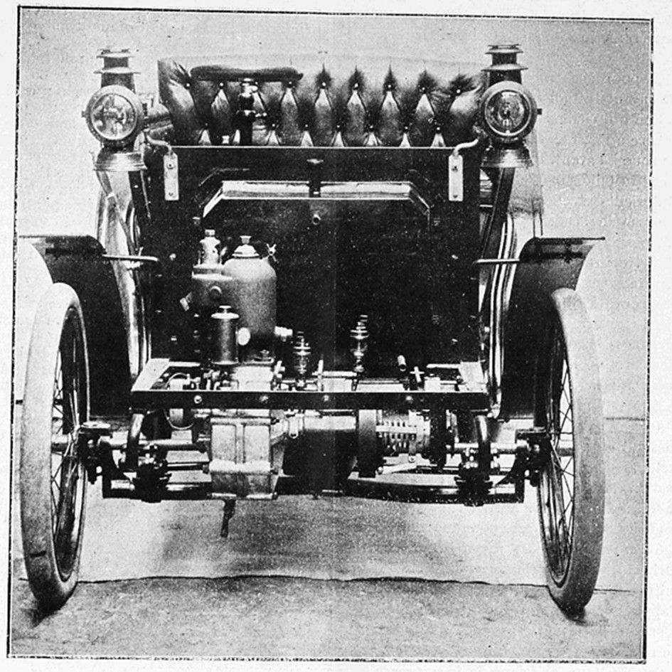
The Roulleau and Pilât car with front-wheel drive and steering.
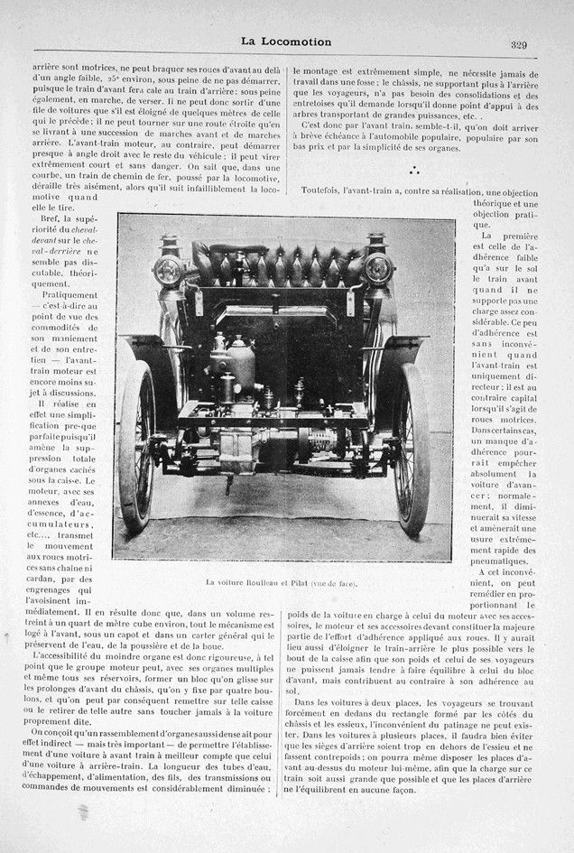
The Roulleau and Pilât car (front view).
Part II:
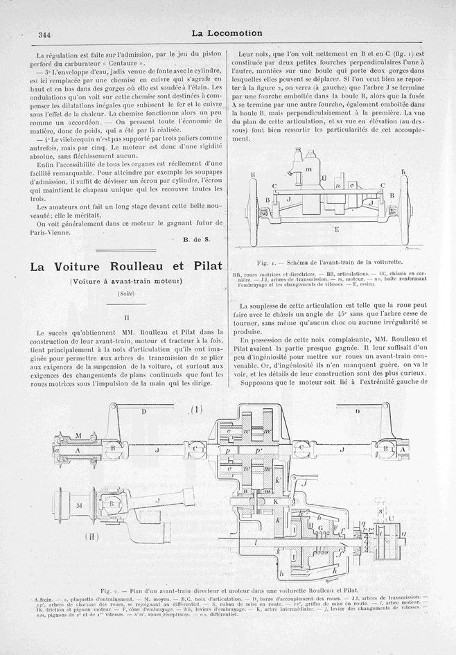
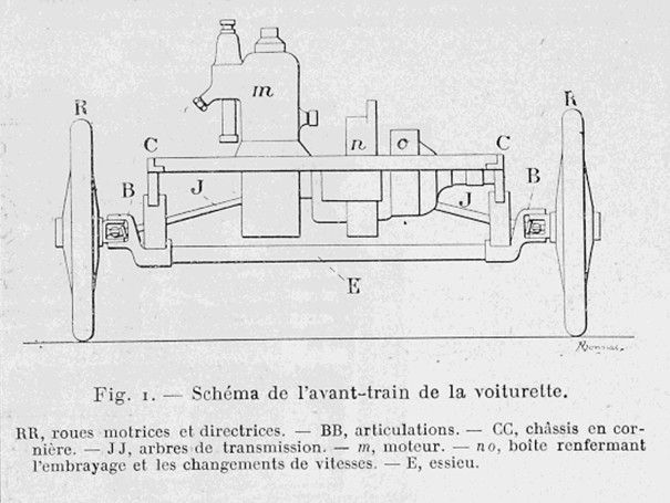
Fig. 1. — Diagram of the front end of the buggy.
RK, drive and steering wheels. — BB, joints. — CC, angle iron chassis. — JJ, drive shafts. — m, engine. — no, box containing the clutch and gear shift. — E, axle.
Fig. 2. — Plan of a steering and drive front end in a Roulleau et Pilât cyclecar.
A, brake. — a, drive plate, — M, hub. — B, C, joint nuts. — D, wheel coupling bar. — JJ, drive shafts. pp‘ shafts for each wheel, connecting to the differential. — S, starter belt. — rr‘ starter claws. — l drive shaft. — IK, friction and drive pinion. — F, clutch cone. — hh, clutch levers. — K, intermediate shaft. — j, gear shift lever. nm, 2nd and 1st gear pinions. — n’m‘ drive wheels. — 00, differential.
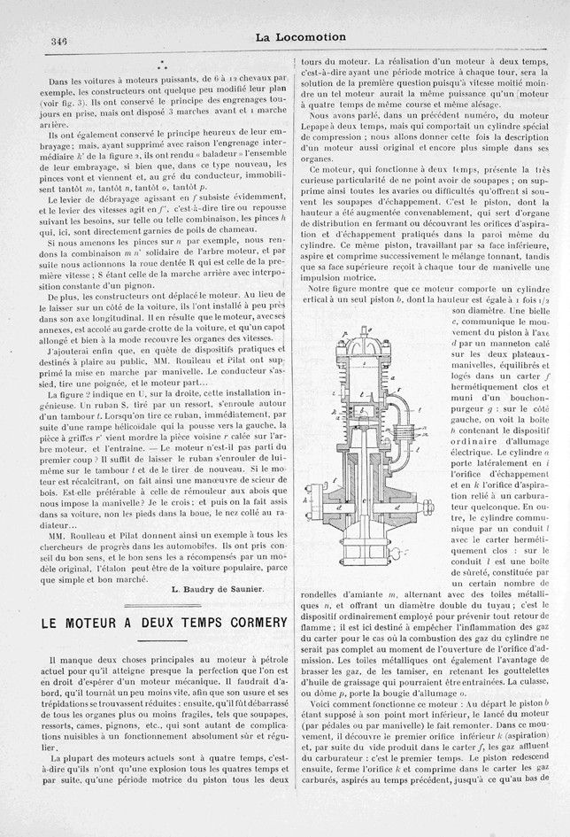
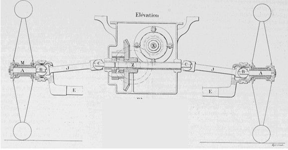
Fig. 3. — Elevation and plan of the front axle in a car.
Elevation. — A, steering knuckle. — a, hub drive component via the steering knuckle, — B,C, transmission shaft joints. — JJ, transmission shafts. — X, drive shaft. — Z, intermediate shaft.
Plan. — ff‘, grooves for the clutch and gear shift forks. — F, clutch spring. — hh‘, clutch levers. — m’S, reverse gear. — n’R, first gear. — o’Q, second gear. — p’P, third gear. — Z, intermediate shaft ending in angle gear z. — W, angle wheel resting on the differential