


This article explains the latest 1909 Christie designed racer. It should encompass all experience, gained with the previous models. This writing is so meticulous, that it gives me the impression, Walter Christie himself has written this.

Text and jpegs by courtesy of hathitrust.org www.hathitrust.org, compiled by motorracinghistory.com
The Automobile, Vol. XXI (21), No. 6, August 5, 1909
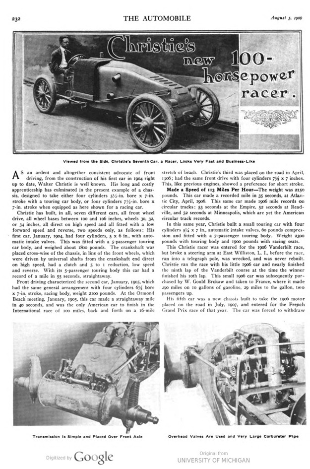
Christie’s new 100-horsepower racer.
AS an ardent and altogether consistent advocate of front driving, from the construction of his first car in 1904 right up to date, Walter Christie is well known. His long and costly apprenticeship has culminated in the present example of a chassis, designed to take either four cylinders 5½-in. bore x 7-in. stroke with a touring car body, or four cylinders 7½-in. bore x 7-in. stroke when equipped as here shown for a racing car.
Christie has built, in all, seven different cars, all front wheel drive, all wheel bases between 100 and 106 inches, wheels 30, 32, or 34 inches, all direct on high speed and all fitted with a low forward speed and reverse, two speeds only, as follows: His first car, January, 1904, had four cylinders, 5 x 6 in., with automatic intake valves. This was fitted with a 5-passenger touring car body, and weighed about 1800 pounds. The crankshaft was placed cross-wise of the chassis, in line of the front wheels, which were driven by universal shafts from the crankshaft end direct on high speed, had a clutch and 5 to 1 reduction, low speed and reverse. With its 5-passenger touring body this car had a record of a mile in 55 seconds, straightaway.
Front driving characterized the second car, January, 1905, which had the same general arrangement with four cylinders 6¼ bore x 7-in. stroke, racing body, weight 2100 pounds. At the Ormond Beach meeting, January, 1905, this car made a straightaway mile in 40 seconds, and was the only American car to finish in the International race of 100 miles, back and forth on a 16-mile stretch of beach. Christie’s third was placed on the road in April, 1906; had the same front drive with four cylinders 7-1/8 x 7 inches. This, like previous engines, showed a preference for short stroke.
Made a Speed of 113 Miles Per Hour – The weight was 2150 pounds. This car made a recorded mile in 35 seconds, at Atlantic City, April, 1906. This same car made 1906 mile records on circular tracks: 53 seconds at the Empire, 52 seconds at Readville, and 52 seconds at Minneapolis, which are yet the American circular track records.
In this same year, Christie built a small touring car with four cylinders 5¼ x 7 in., automatic intake valves, 60 pounds compression and fitted with a 7-passenger touring body. Weight 2300 pounds with touring body and 1900 pounds with racing seats.
This Christie racer was entered for the 1906 Vanderbilt race, but broke a steering arm at East Williston, L. I., before the race, ran into a telegraph pole, was wrecked, and was never rebuilt. Christie ran the race with his little 1906 car and nearly finished the ninth lap of the Vanderbilt course at the time the winner finished his 10th lap. This small 1906 car was subsequently purchased by W. Gould Brokaw and taken to France, where it made 290 miles on 10 gallons of gasoline, 29 miles to the gallon, two passengers up.
His fifth car was a new chassis built to take the 1906 motor placed on the road in July, 1907 and entered for the French Grand Prix race of that year. The car was forced to withdraw with a broken valve stem at the end of 235 miles. This car did a mile at Ormond Beach, March, 1908, in 33 seconds, not officially timed.
Sixth on the list was the front drive cab, placed on the road June 1, 1908. The motor is four cylinders, 3¼ x 5 in., 60 pounds compression, all valves mechanically operated.
Seventh and Last Car a High Power Racer – Lucky seven is the number held by the car here shown, which was placed on the road July 8, 1909. This car is fitted with three sets of wheels, 30-inch for circular tracks, 32-inch for road work, and 34-inch for straight-away road or track racing.
This is a long record of experimental cars, all of which were fast, economical of fuel, and showed the advantages of front drive.
Undoubtedly Christie erred in his choice of automatic intake valves, abandoned in favor of mechanical operation in the last two models, the cab and 1909 racer.
Herewith is shown the car which was built to show the advantages of the front drive under all conditions, and is fitted to take not only the three sets of wheels, but two different motors. One, here shown, for racing, four cylinders, 7½ x 7 in., and one for touring, four cylinders, either 5½ x 7 cr 6 x 7 in., so, with this one chassis all conditions can be met to give needful comparisons with rear driven cars.
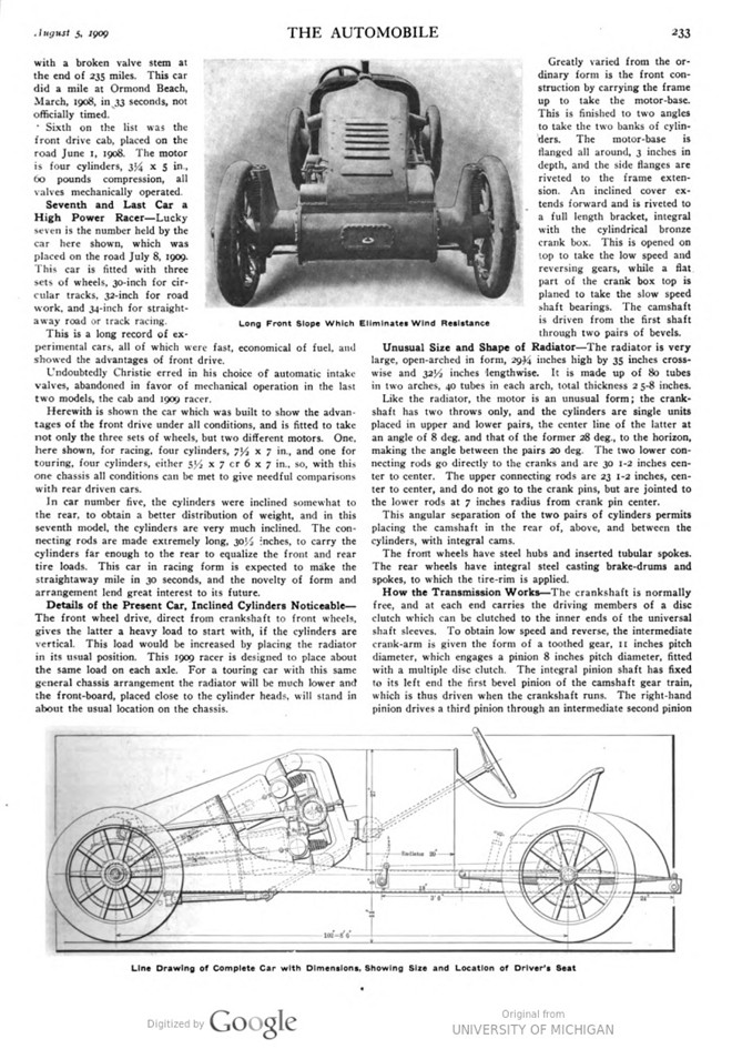
In car number five, the cylinders were inclined somewhat to the rear, to obtain a better distribution of weight, and in this seventh model, the cylinders are very much inclined. The con- necting rods are made extremely long, 30½ inches, to carry the cylinders far enough to the rear to equalize the front and rear tire loads. This car in racing form is expected to make the straightaway mile in 30 seconds, and the novelty of form and arrangement lend great interest to its future.
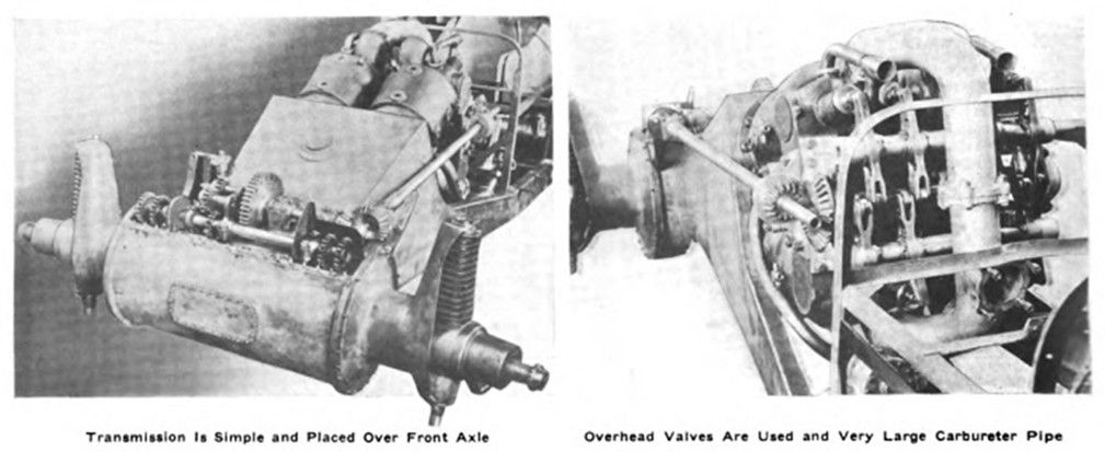
Details of the Present Car, Inclined Cylinders Noticeable – The front wheel drive, direct from crankshaft to front wheels, gives the latter a heavy load to start with, if the cylinders are vertical. This load would be increased by placing the radiator in its usual position. This 1909 racer is designed to place about the same load on each axle. For a touring car with this same general chassis arrangement the radiator will be much lower and the front-board, placed close to the cylinder heads, will stand in about the usual location on the chassis.
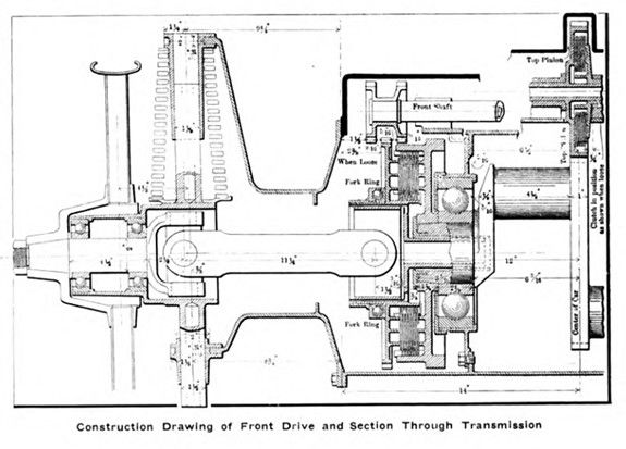
Greatly varied from the ordinary form is the front construction by carrying the frame up to take the motor-base. This is finished to two angles to take the two banks of cylinders. The motor-base is flanged all around, 3 inches in depth, and the side flanges are riveted to the frame extension. An inclined cover extends forward and is riveted to a full-length bracket, integral with the cylindrical bronze crank box. This is opened on top to take the low speed and reversing gears, while a flat. part of the crank box top is planed to take the slow speed shaft bearings. The camshaft is driven from the first shaft through two pairs of bevels.
Unusual Size and Shape of Radiator – The radiator is very large, open-arched in form, 2934 inches high by 35 inches crosswise and 32½ inches lengthwise. It is made up of 80 tubes in two arches, 40 tubes in each arch, total thickness 2 5-8 inches.
Like the radiator, the motor is an unusual form; the crankshaft has two throws only, and the cylinders are single units placed in upper and lower pairs, the center line of the latter at an angle of 8 deg. and that of the former 28 deg., to the horizon, making the angle between the pairs 20 deg. The two lower connecting rods go directly to the cranks and are 30 1-2 inches center to center. The upper connecting rods are 23 1-2 inches, center to center, and do not go to the crank pins, but are jointed to the lower rods at 7 inches radius from crank pin center.
This angular separation of the two pairs of cylinders permits placing the camshaft in the rear of, above, and between the cylinders, with integral cams. The front wheels have steel hubs and inserted tubular spokes. The rear wheels have integral steel casting brake-drums and spokes, to which the tire-rim is applied.
How the Transmission Works – The crankshaft is normally free, and at each end carries the driving members of a disc clutch which can be clutched to the inner ends of the universal shaft sleeves. To obtain low speed and reverse, the intermediate crank-arm is given the form of a toothed gear, 11 inches pitch diameter, which engages a pinion 8 inches pitch diameter, fitted with a multiple disc clutch. The integral pinion shaft has fixed to its left end the first bevel pinion of the camshaft gear train, which is thus driven when the crankshaft runs. The right-hand pinion drives a third pinion through an intermediate second pinion to obtain reverse; it also engages a transfer pinion, and between the reverse pinion and the transfer pinion, there is placed a gear fixed to a sliding shaft.
Operation of this drive is as follows: With all clutches disengaged, crankshaft driving the camshaft gears and camshaft only, the motor is started by giving a double stroke to the hand operated gang of four charging pumps. Then, with the motor working, the top pinion clutch is engaged, starting the reverse and forward slow-speed pinions; according to direction desired, the front shaft is made to slide to the right for backing or to the left for slow forward. Front shaft pinions slide into engagement with universal-sleeve gears, and so start the front wheels. The front shaft is made to slide endwise by rocking a vertical fork-shaft interlinked with the direct drive clutch fork, so that when the direct fork is moved the front shaft slides the low speed pinion out of engagement before the direct drive clutch is operatively engaged. Reverse is not interlinked with direct clutch.
Differential Is Eliminated – This form of front drive does not include a „differential.“ Two pairs of pinions, one pair on each end of the front shaft, have considerable „lost motion,“ so that the outer wheel can overrun the front shaft in turning corners. The regular touring car drive will include a bevel balance gear on the front shaft. For turning very short corners with the direct drive, the clutch pressure is partially removed by foot pressure. For rounding large radius curves, the drive takes care of itself. This method of gaining the advantages of the differential without its inherent complications is more than praiseworthy.
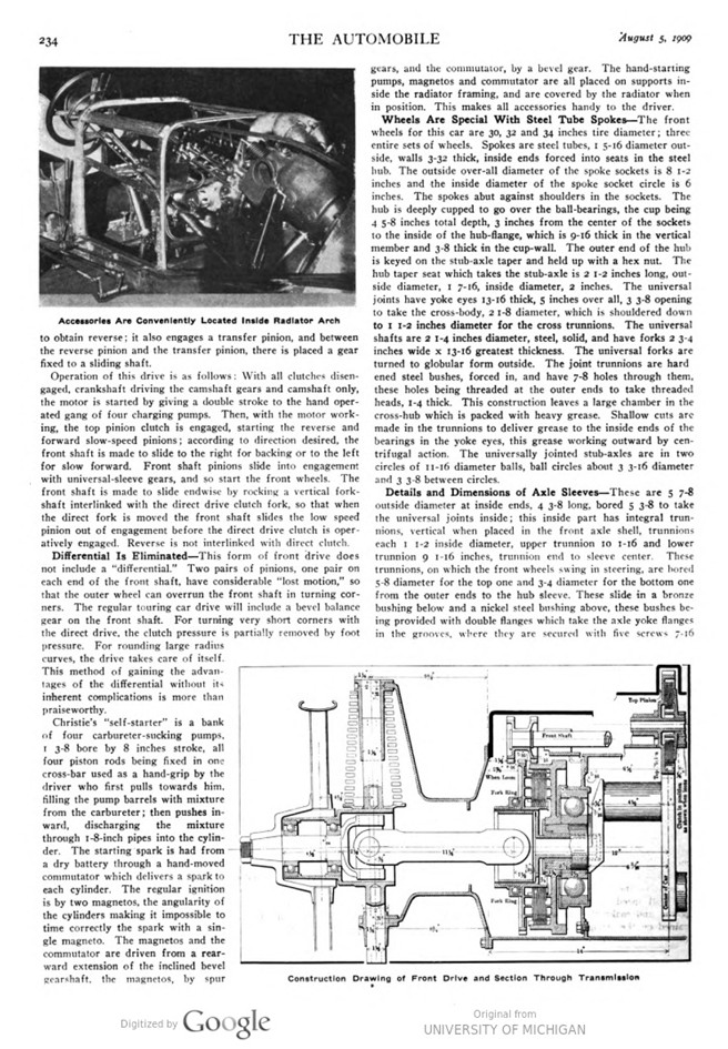
Christie’s „self-starter“ is a bank of four carbureter-sucking pumps, 1 3-8 bore by 8 inches stroke, all four piston rods being fixed in one cross-bar used as a hand-grip by the driver who first pulls towards him, filling the pump barrels with mixture from the carbureter; then pushes in- ward, discharging the mixture through 1-8-inch pipes into the cylinder. The starting spark is had from a dry battery through a hand-moved commutator which delivers a spark to each cylinder. The regular ignition is by two magnetos, the angularity of the cylinders making it impossible to time correctly the spark with a single magneto. The magnetos and the commutator are driven from a rearward extension of the inclined bevel gearshaft, the magnetos, by spur gears, and the commutator, by a bevel gear. The hand-starting pumps, magnetos and commutator are all placed on supports inside the radiator framing, and are covered by the radiator when in position. This makes all accessories handy to the driver.
Wheels Are Special With Steel Tube Spokes – The front wheels for this car are 30, 32 and 34 inches tire diameter; three entire sets of wheels. Spokes are steel tubes, 1 5-16 diameter outside, walls 3-32 thick, inside ends forced into seats in the steel hub. The outside over-all diameter of the spoke sockets is 8 1-2 inches and the inside diameter of the spoke socket circle is 6 inches. The spokes abut against shoulders in the sockets. The hub is deeply cupped to go over the ball-bearings, the cup being 4 5-8 inches total depth, 3 inches from the center of the sockets to the inside of the hub-flange, which is 9-16 thick in the vertical member and 3-8 thick in the cup-wall. The outer end of the hub is keyed on the stub-axle taper and held up with a hex nut. The hub taper seat which takes the stub-axle is 2 1-2 inches long, outside diameter, I 7-16, inside diameter, 2 inches. The universal joints have yoke eyes 13-16 thick, 5 inches over-all, 3 3-8 opening to take the cross-body, 2 1-8 diameter, which is shouldered down to I 1-2 inches diameter for the cross trunnions. The universal shafts are 2 1-4 inches diameter, steel, solid, and have forks 2 3-4 inches wide x 13-16 greatest thickness. The universal forks are turned to globular form outside. The joint trunnions are hardened steel bushes, forced in, and have 7-8 holes through them, these holes being threaded at the outer ends to take threaded heads, 1-4 thick. This construction leaves a large chamber in the cross-hub which is packed with heavy grease. Shallow cuts are made in the trunnions to deliver grease to the inside ends of the bearings in the yoke eyes, this grease working outward by centrifugal action. The universally jointed stub-axles are in two circles of 11-16 diameter balls, ball circles about 3 3-16 diameter and 3 3-8 between circles.
Details and Dimensions of Axle Sleeves – These are 5 7-8 outside diameter at inside ends, 4 3-8 long, bored 5 3-8 to take the universal joints inside; this inside part has integral trunnions, vertical when placed in the front axle shell, trunnions each 1-2 inside diameter, upper trunnion 10 1-16 and lower trunnion 9 1-16 inches, trunnion end to sleeve center. These trunnions, on which the front wheels swing in steering, are bored 5-8 diameter for the top one and 3-4 diameter for the bottom one from the outer ends to the hub sleeve. These slide in a bronze bushing below and a nickel steel bushing above, these bushes being provided with double flanges which take the axle yoke flanges in the grooves, where they are secured with five screws 7-16 diameter. The outer member of the axle sleeve is 4 3-4 outside diameter and 4 3-8 inside diameter, flanged to stop the ball cups, as before described.
This axle sleeve has about 5 1-2 inches clear vertical travel by the sliding of its integral trunnions up and down.
Front springs are volute (spiral), rectangular in section, 11-16 X 1-4, 4 1-2 inside, outside diameter at bottom and 3 1-4 outside diameter at top end, 18 turns, 17 spaces 1-4 inch wide, giving 4 1-4 inches spring closure. This spring closes under 800 pounds load and carries about 600 pounds when standing still on the road. The lower end of the spring rests on a flanged steel washer, 4 3-4 inches outside diameter.
Because of greater length, owing to the spring placing, the top trunnion is made the heavier, and is supported in a nickel steel sleeve, while the shorter and lighter lower trunnion is supported in a bronze sleeve.
The steering arms are nickel steel forgings, oval section at the root, about 1 1-2 x 1 1-8, applied to the large part of the axle sleeves and retained with II rivets, each 5-16 diameter. The steering arm eyes, I 1-4 diameter by 9-16 thick, with 5-8 diameter pin-holes, are about 12 1-2 inches radius.
Another Strong Supporter of the Disc Clutch – In the Christie front drive there are three separate disc clutches, one in the top pinion, and one at each end of the crankshaft. The discs are all spring tempered, saw steel, ground flat. The top pinion clutch has 10 discs, 6 1-8 inches effective outside diameter. The direct drive clutches are each 18 discs, 11 3-8 effective outside diameter x 7 3-16 inches effective inside diameter. The top pinion clutch is normally disengaged, has no spring, and is engaged by pushing the engagement-disc capped-and-pointed-sleeve- end into engagement with the short arm of the engaging bell- crank, the points of contact being hardened. The crankshaft clutches are normally engaged by spring pressure applied to the clutch linkage; the engaging fork ends, hardened, bear against a hardened ball thrust bearing ring. The fork hand lever is in a quadrant and is latched to hold the clutch out.
All principal members are carried on ball-bearings, Hess-Bright, including the crankshaft, camshaft, and bevel gear shaft. The front and rear wheels are on ball-bearings; the crankshaft bearings are very large, 8 7-8 inches outside diameter, balls 1 5-8 inches diameter.
Front axle is a cylindrical bronze casting, 15 1-8 inches diameter, 3-16 wall thickness, flanged at each end to take bronze heads, which are cast integral with the spring forks. The diameter of the spring forks member is 7 1-2 inches, walls 3-16 thick.
The rear axle is a steel tube, 2 1-4 diameter, with 1-4-inch walls, the axles 1 3-4 diameter, entering the tubular body, retained by shrinking and pinning.
Naturally, the Springs Are Decidedly Different – The rear springs are semi-elliptic, 48 x 2 inches, 5 leaves, top 3 leaves banded together, front eye jointed to frame, rear eye linked to frame by links in tension, spring passing under axle. The rear axle travels up and down in slots in the manganese bronze castings which form intermediate members of the frame sides. The frame sides are of sheet steel 1-8 thick, 5 inches greatest depth in rear of motor x 1 1-2 inches wide. The greatest side-frame depth occurs at the top corner of the motor base, and is 21 3-4 inches. There are two widths to the frame, 30 inches rear to front of radiator, then drawn in on a straight taper to 18 1-2 inches width where the frame front end joins the cylindrical box which forms the body of the front axle.
Save for unusual connecting rod length, the motor is of ordinary water-cooled construction, cylinder bore 7 1-2 inches, all valve ports 3 inches in diameter, all valves mechanically operated and all located in the cylinder heads. The piston packing is four snap rings, all above the piston pin. The camshaft is midway between the cylinder heads, and the valve action is by beams turning on hollow shafts.
Water circulation is by a two-pinion water pump, chain driven from the rearward prolongation of the side shaft.
The crankshaft is a steel forging, 19 inches over-all, having two crank-throws, 3 1-2 inches radius, cranks set at 180 degrees. The crankshaft has journals 3 1-2 inches diameter at each end, in Hess-Bright ball-bearings about 8 13-16 diameter, 1 3-8 diameter balls. The crank-arms are each 7-8 thick. What would be the middle crank-arm is a gear, I inch face, 11 inches pitch diameter, which engages the 8-inch pitch diameter pinion to drive the top shaft. The crank-wrists are 3 inches diameter x 4 I-2 inches long. The connecting rod wrist bearings are offset on the rod. The ends of the crankshaft are tapered and fitted with nuts to force the friction disc clutch cup onto the taper, which is about 5 degrees.
The brakes are internal, only, in the rear wheel hub-drums, are 14 inches diameter x 3 1-2 inches face, and are fiber-faced expanding bands, one end of the band fixed and the other end jointed to the short arm of the brake rock shaft.
Carbureter an Original Design with One Standpipe – The carbureter is Christie’s own construction, a float feed with a single standpipe, an automatic air intake and a mechanically operated air admission which is linked to the throttle, so as to decrease air supply as the volume of cylinder charge is diminished. The carbureter supply pipe is of very large diameter.
Steering action is by a pinion and rack, hand wheel 18 inches in diameter, steering shaft pinion 2 1-2 inches pitch diameter, one turn of the hand-wheel to full sweep of the front wheels. The spark control is forward of the hand wheel and stands upright for ordinary position. The throttle control is at right side and forward of the hand wheel. There are three pedals on the footboard, one for the brake and two friction clutch pedals. There is a small lever latched in its quadrant, at the driver’s right, which disengages the normally spring engaged, high-speed clutches, these being of the multiple disc type.
Photo captions.
Page 232.
Viewed from the Side, Christie’s Seventh Car, a Racer, Looks Very Fast and Business-Like
Transmission Is Simple and Placed Over Front Axle
Overhead Valves Are Used and Very Large Carbureter Pipe
Page 233.
Long Front Slope Which Eliminates Wind Resistance
Line Drawing of Complete Car with Dimensions, Showing Size and Location of Driver’s Seat
Page 234.
Accessories Are Conveniently Located Inside Radiator Arch
Construction Drawing of Front Drive and Section Through Transmission