


This article in Scientific American early 1905, describes the first Christie front-wheel drive car. Especially interesting is the section where the connection of engine crankshaft to front wheels is described. It will take some time to really understand, what genious idea Walter Christie had.


Text and jpegs by courtesy of hathitrust.org www.hathitrust.org, compiled by motorracinghistory.com
Scientific American, Vol. 92, Issue 4, January 28, 1905
A NEW AMERICAN AUTOMOBILE.
Our illustrations depict a distinctly American machine of a new type, the original of which made its debut at Ormond Beach a year ago, and despite cut cylinders from running out of oil, made the fast time of a mile a minute. Since then Mr. Walter Christie, of this city, the inventor of the car, has constructed a much larger racer, and with this he has gone to Florida again, with the hope of making some speed records. If he is successful this year at Ormond during the present week, he may afterward enter the long-distance road race, which is to be run off in Cuba. The new car, as can be seen from the photographs, is quite simple.
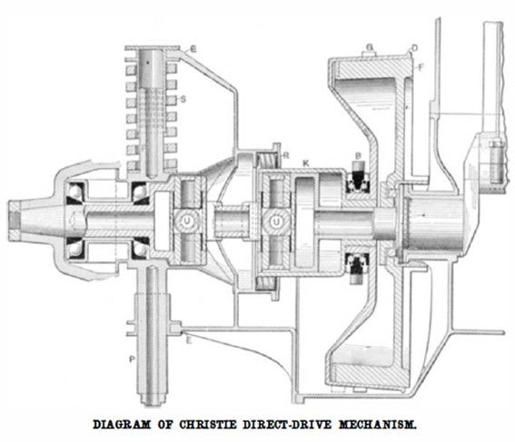
It consists of a front axle formed of the motor crank case and suitably attached to the side bars of the frame. The ends of the crank case are brought out somewhat in the shape of a forked steering knuckle (EE in diagram), and the upper part of the fork rests upon a cap which slides over the vertical part, P, of the steering spindle, upon which it is supported by a stiff coiled spring.
The front wheels revolve on ball bearings on the steering spindles, being driven by universally jointed shafts, which pass through the hollow spindles and are keyed in the outer ends of the wheel hubs. The two universal joints are seen at UU. The rear wheels are also fitted with ball bearings and band brakes. It will thus be seen that while the motor is on the front end of the car, as is the case with most modern automobiles, the construction differs from that usually employed, in that the motor is set transversely on the chassis and drives the front wheels direct. All that part of the car behind the front axle is a trailer for the axle, and as the machine draws instead of pushing itself, there is not liable to be trouble from skidding; besides, this method of propulsion consumes less power, as determined by electrical tests.
The chief charm of the new construction, however, is the direct application of power to the wheels. Each flywheel, F, of the motor forms a conical clutch inlaid with segments of leather, which does away with the usual method of riveting on the leather in a band. These cone clutches engage drums, D, which slide on and drive through a considerable number of keys located at K, the inner end of the short universally jointed drive shaft that has one bearing in the motor crankshaft and the other in the wheel, to the hub of which it is keyed.
The driving sleeve or cup attached to D has a bearing, R, on rollers in the crank case extension. This sleeve and drum, D, is slid to the left by ball bearing fork, B, when flywheel clutch is out. The middle section of the inner drive shaft is that having the two forks for the universal joints, while the outer end drives the wheel as mentioned above. The pins used in the universal joints are hollow and are packed in grease. A 5,000-mile test has shown practically no wear here. When the clutches are in, the motor crankshaft is locked to the wheels. No differential is provided for the direct drive on the present car, but one could be incorporated in the flywheel or wheel hub should a commercial car be built and a differential be found necessary. At present the springs used to hold the clutches in place are light enough to allow sufficient slippage to take care of the differential movement. When on the low speed or reverse, a differential on the countershaft is in use.
The drums which the flywheel cones engage each carry a large gear ring, G, on their periphery, and these rings are driven by small gears on the ends of a countershaft, which receives its motion from a short countershaft above it, driven at a reduced speed by a large gear on the two-to-one cam shaft that operates the exhaust valves. By engaging one or the other of two gears on this shaft with a gear on the main countershaft, and throwing in the small cone clutch, the low speed and reverse are obtained.
Thus, it will be seen that the present car has all the essential parts of any ordinary automobile, including the differential; and it is by no means as much of a freak as a car exhibited at the Paris show, which will be found described in the SUPPLEMENT for January 7. This car has no low speed or reverse, the latter being obtained by reversing the motor, and the drive being through a friction clutch and longitudinal driving shaft to a countershaft, and thence by chains to the rear wheels. A specially constructed clutch that can be allowed to slip without damage replaces the low-speed gear. A combination of this idea with that of Mr. Christie would give an ideally simple car.
The four-cylinder motor used on the present car is of about 70 horse-power. It has a 6¼-inch bore by 6¾-inch stroke, and will drive the car 90 miles an hour when making 792 R. P. M. The 40-inch wheels make one revolution with every turn of the engine crankshaft, and the car advances 10 feet per revolution. The inlet valves of the motor are automatic and are eight in number for each cylinder, being arranged in two circular plates, as shown. There are 32 inlet valves altogether, and all are of the fiat-seated variety. A single large exhaust valve is used for each cylinder. An automatic carbureter having a multiplicity of tiny automatic valves (similar to the inlet valves of the motor), for admitting the auxiliary air, is used. The gasoline tank is under the rear seat; the fuel being forced to the carbureter by air pressure. The ignition is by jump spark from coils with vibrators and a three-cell storage battery. The contact device is a ring of fiber with steel contacts. A steel roller moving around within the ring is used to make the contact.
The rear part of the bonnet is made up of twelve sections of finned radiating pipes, there being eight 5-16-inch pipes 64 inches long and carrying 340 5×1-inch fins to a section. A total of over 20,000 square inches of radiating surface is thus obtained. The pipes are of copper and the fins of aluminium, and both are coated with lampblack. From a vertical cylindrical copper tank in front of the radiator, the water is forced by a gear-driven gear pump through the radiator and into the bottom of the water jacket on each side of the motor. A pipe running across the top of the motor and connecting with the water jacket between each cylinder, carries the hot water to the vertical cylinder, thus completing the circuit. The controlling levers, spark coils, sight-feed oiler and water-pressure gage are all at the rear, directly before the driver. The ignition current may be instantly cut by the switch on the steering wheel.
Photo captions.
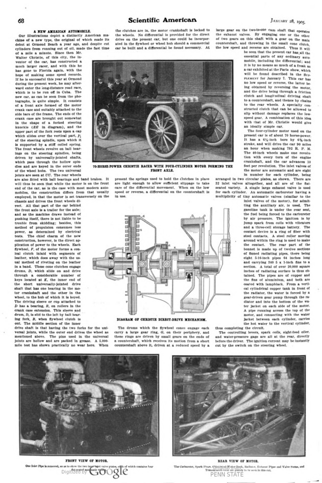
70-HORSE-POWER CHRISTIE RACER WITH FOUR-CYLINDER MOTOR FORMING THE FRONT AXLE.
DIAGRAM OF CHRISTIE DIRECT-DRIVE MECHANISM.
FRONT VIEW OF MOTOR.
One Inlet Pipe Is removed, so as to show the two large inlet, valve plates, each of which contains four fiat-seated automatic valves.
REAR VIEW OF MOTOR. The Carburetor, Spark Plugs, Cylindrical Water Tank, Radiator, Exhaust Pipes and Valve Stems, and Transmission Gear are plainly to be seen in this cut.