


Text and jpegs by courtesy of hathitrust.org www.hathitrust.org, compiled by motorracinghistory.com
Motor Age, Vol. XLI (41), No. 25, June 22, 1922
250 SPARKS PER SECOND
Tremendous Duties Imposed Upon the Ignition System of a Straight Eight Engine in a 500-Mile Race – How Battery Ignition is Designed for Successful Operation at Sustained High Speeds
By A. H. PACKER
THE design of battery ignition for use with high-speed engines, especially where those engines have more than the customary four or six cylinders, involves a number of problems which should be of special interest in view of the fact that the impression has prevailed that battery ignition was effective only at comparatively low speeds and that sparks from a battery ignition system were necessarily very weak at high speeds.
While it is true that any battery ignition system will have a speed at which the heat of the spark begins to decrease, it is still perfectly possible to have that speed above any desired point so that from a practical standpoint the solution is not so complicated as it may first appear.
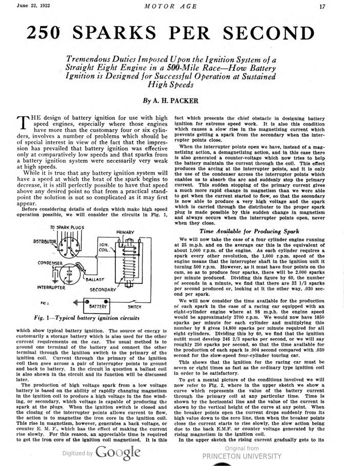
Before considering details of design which make high speed operation possible, we will consider the circuits in Fig. 1, which show typical battery ignition. The source of energy is customarily a storage battery which is also used for the other current requirements on the car. The usual method is to ground one terminal of the battery and connect the other terminal through the ignition switch to the primary of the ignition coil. Current through the primary of the ignition coil then goes across a pair of interrupter points to ground and back to battery. In the circuit in question a ballast coil is also shown in the circuit, and its function will be discussed later.
The production of high voltage spark from a low voltage battery is based on the ability of rapidly changing magnetism in the ignition coil to produce a high voltage in the fine winding, or secondary, which voltage is capable of producing the spark at the plugs. When the ignition switch is closed and the closing of the interrupter points allows current to flow, the action is to magnetize the iron core in the ignition coil. This rise in magnetism, however, generates a back voltage, or counter E. M. F., which has the effect of making the current rise slowly. For this reason, an appreciable time is required to get the iron core of the ignition coil magnetized. It is this fact which presents the chief obstacle in designing battery ignition for extreme speed work. It is also this condition which causes a slow rise in the magnetizing current which prevents getting a spark from the secondary when the interrupter points close.
When the interrupter points open we have, instead of a magnetizing action, a demagnetizing action, and in this case there is also generated a counter-voltage which now tries to help the battery maintain the current through the coil. This effect produces the arcing at the interrupter points, and it is only the use of the condenser across the interrupter points which enables us to absorb the arc and suddenly stop the primary current. This sudden stopping of the primary current gives a much more rapid change in magnetism than we were able to get when the current started to flow, so that the secondary is now able to produce a very high voltage and the spark which is carried through the distributer to the proper spark plug is made possible by this sudden change in magnetism and always occurs when the interrupter points open, never when they close.
Time Available for Producing Spark
We will now take the case of a four-cylinder engine running at 25 m.p.h. and on the average car this is the equivalent of about 1,000 r.p.m. of the engine. As each cylinder requires a spark every other revolution, the 1,000 r.p.m. speed of the engine means that the interrupter shaft in the ignition unit it turning 500 r.p.m. However, as it must have four points on the cam, so as to produce four sparks, there will be 2,000 sparks per minute produced. Dividing this figure by 60, the number of seconds in a minute, we find that there are 33 1/3 sparks per second produced or, looking at it the other way, .030 second per spark.
We will now consider the time available for the production of each spark in the case of a racing car equipped with an eight-cylinder engine where at 98 m.p.h. the engine speed would be approximately 3700 r.p.m. We would now have 1850 sparks per minute for each cylinder and multiplying this number by 8 gives 14,800 sparks per minute required for all eight cylinders. Dividing this by 60, we find that the ignition outfit must develop 246 2/3 sparks per second, or we will say roughly 250 sparks per second, so that the time available for the production of each spark is .004 second compared with .030 second for the slow-speed four-cylinder touring car.
This shows that the ignition for the racing car must be seven or eight times as fast as the ordinary type ignition coil in order to be satisfactory.
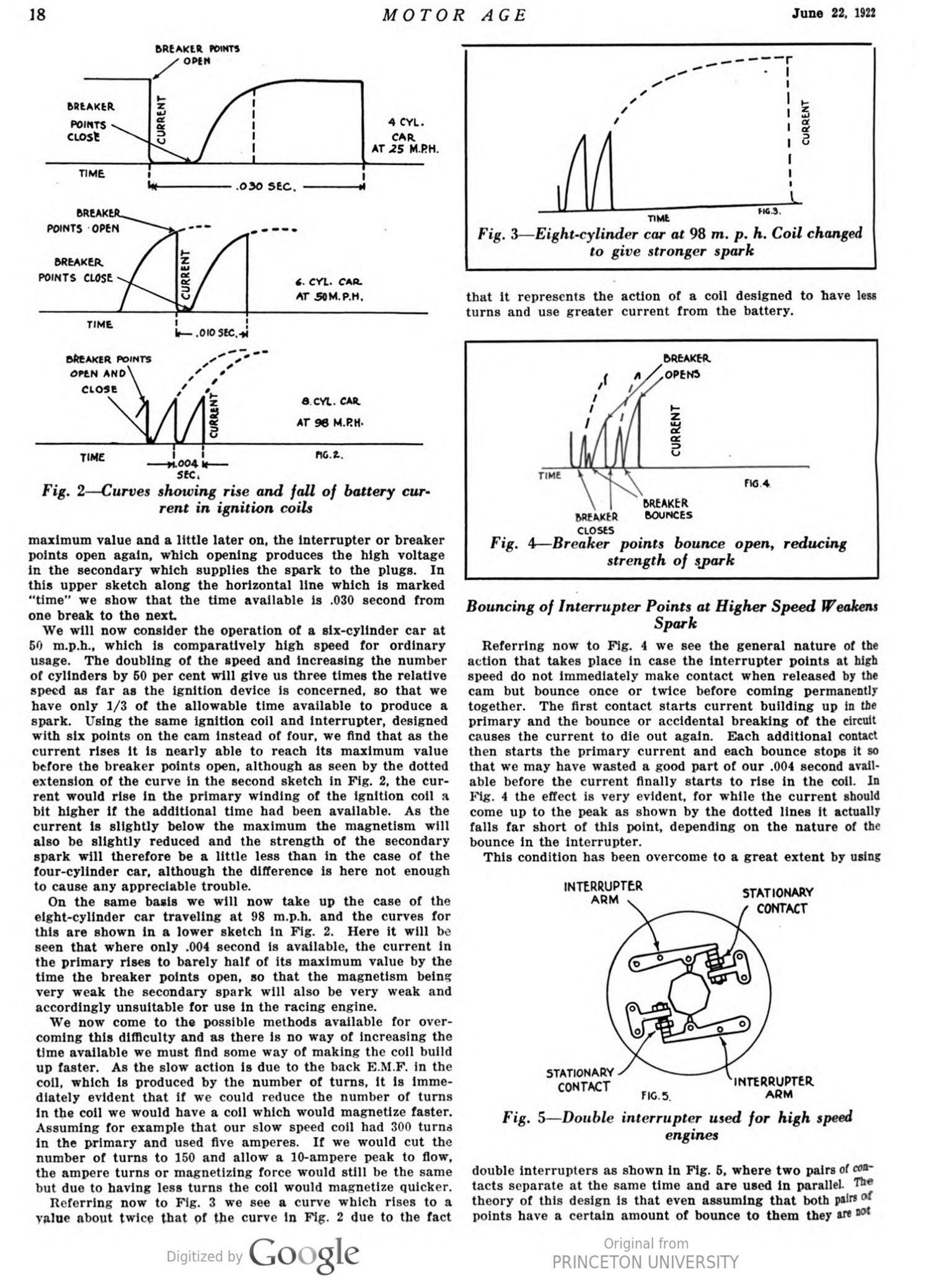
To get a mental picture of the conditions involved we will now refer to Fig. 2, where in the upper sketch we show a curve which represents the value of the battery current through the primary coil at any particular time. Time is shown by the horizontal line and the value of the current is shown by the vertical height of the curve at any point. When the breaker points open the current drops suddenly from its high value down to the zero line, then when the breaker points close the current starts to rise slowly, the slow action being due to the back E.M.F. or counter voltage generated by the rising magnetism in the ignition coil.
In the upper sketch the rising current gradually gets to its maximum value and a little later on, the interrupter or breaker points open again, which opening produces the high voltage in the secondary which supplies the spark to the plugs. In this upper sketch along the horizontal line which is marked „time“ we show that the time available is .030 second from one break to the next.
We will now consider the operation of a six-cylinder car at 50 m.p.h., which is comparatively high-speed for ordinary usage. The doubling of the speed and increasing the number of cylinders by 50 per cent will give us three times the relative speed as far as the ignition device is concerned, so that we have only 1/3 of the allowable time available to produce a spark. Using the same ignition coil and interrupter, designed with six points on the cam instead of four, we find that as the current rises it is nearly able to reach its maximum value before the breaker points open, although as seen by the dotted extension of the curve in the second sketch in Fig. 2, the current would rise in the primary winding of the ignition coil a bit higher if the additional time had been available. As the current is slightly below the maximum the magnetism will also be slightly reduced and the strength of the secondary spark will therefore be a little less than in the case of the four-cylinder car, although the difference is here not enough to cause any appreciable trouble.
On the same basis we will now take up the case of the eight-cylinder car traveling at 98 m.p.h. and the curves for this are shown in a lower sketch in Fig. 2. Here it will be seen that where only .004 second is available, the current in the primary rises to barely half of its maximum value by the time the breaker points open, so that the magnetism being very weak the secondary spark will also be very weak and accordingly unsuitable for use in the racing engine.
We now come to the possible methods available for overcoming this difficulty and as there is no way of increasing the time available we must find some way of making the coil build up faster. As the slow action is due to the back E.M.F. in the coil, which is produced by the number of turns, it is immediately evident that if we could reduce the number of turns in the coil we would have a coil which would magnetize faster. Assuming for example that our slow speed coil had 300 turns in the primary and used five amperes. If we would cut the number of turns to 150 and allow a 10-ampere peak to flow, the ampere turns or magnetizing force would still be the same but due to having less turns the coil would magnetize quicker.
Referring now to Fig. 3 we see a curve which rises to a value about twice that of the curve in Fig. 2 due to the fact that it represents the action of a coil designed to have less turns and use greater current from the battery.
Bouncing of Interrupter Points at Higher Speed Weakens Spark
Referring now to Fig. 4 we see the general nature of the action that takes place in case the interrupter points at high speed do not immediately make contact when released by the cam but bounce once or twice before coming permanently together. The first contact starts current building up in the primary and the bounce or accidental breaking of the circuit causes the current to die out again. Each additional contact then starts the primary current and each bounce stops it so that we may have wasted a good part of our .004 second available before the current finally starts to rise in the coil. In Fig. 4 the effect is very evident, for while the current should come up to the peak as shown by the dotted lines it actually falls far short of this point, depending on the nature of the bounce in the interrupter.
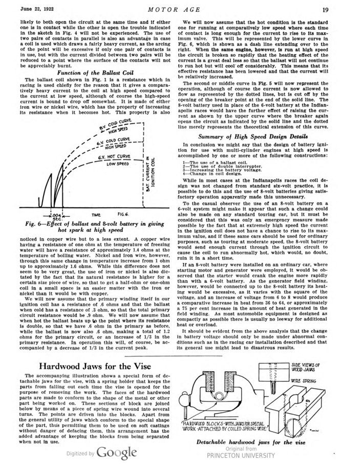
This condition has been overcome to a great extent by using double interrupters as shown in Fig. 5, where two pairs of contacts separate at the same time and are used in parallel. The theory of this design is that even assuming that both pairs of points have a certain amount of bounce to them they are not likely to both open the circuit at the same time and if either one is in contact while the other is open the trouble indicated in the sketch in Fig. 4 will not be experienced. The use of two pairs of contacts in parallel is also an advantage in case a coil is used which draws a fairly heavy current, as the arcing of the point will be excessive if only one pair of contacts is in use, but with the current divided between two pairs will be reduced to a point where the surface of the contacts will not be appreciably burnt.
Function of the Ballast Coil
The ballast coil shown in Fig. 1 is a resistance which in racing is used chiefly for the reason that it gives a comparatively heavy current to the coil at high speed compared to the current at low speed, although of course the high-speed current is bound to drop off somewhat. It is made of either iron wire or nickel wire, which has the property of increasing its resistance when it becomes hot. This property is also noticed in copper wire but to a less extent. A copper wire having a resistance of one ohm at the temperature of freezing water will have a resistance of approximately 1.4 ohms at the temperature of boiling water. Nickel and iron wire, however, through this same change in temperature increase from 1 ohm up to approximately 1.6 ohms. While this difference does not seem to be very great, the use of iron or nickel is also dictated by the fact that its natural resistance is higher for a certain size piece of wire, so that to get a half-ohm or one-ohm coil in a small space is an easier matter with the iron or nickel than it would be with copper.
We will now assume that the primary winding itself in our ignition coil has a resistance of .6 ohms and that the ballast when cold has a resistance of .3 ohm, so that the total primary circuit resistance would be .9 ohm. We will now assume that when hot the ballast heats up to the point where its resistance is double, so that we have .6 ohm in the primary as before, while the ballast is now also .6 ohm, making a total of 1.2 ohms for the primary circuit, or an increase of 1/3 in the primary resistance. In operation this will, of course, be accompanied by a decrease of 1/3 in the current peak.
We will now assume that the hot condition is the standard one for running at comparatively low speed where each time of contact is long enough for the current to rise to its maximum valve. This will be represented by the lower curve in Fig. 6, which is shown as a dash line extending over to the right. When the same engine, however, is run at high speed the circuit is broken so rapidly that the heating effect of the current is a great deal less so that the ballast will not continue to run hot but will cool off considerably. This means that its effective resistance has been lowered and that the current will be relatively increased.
The second or middle curve in Fig. 5 will now represent the operation, although of course the current is now allowed to flow as represented by the dotted lines, but is cut off by the opening of the breaker point at the end of the solid line. The 8-volt battery used in place of the 6-volt battery at the Indianapolis races would have the further effect of raising the current as shown by the upper curve where the breaker again opens the circuit as indicated by the solid line and the dotted line merely represents the theoretical extension of this curve.
Summary of High Speed Design Details
In conclusion we might say that the design of battery ignition for use with multi-cylinder engines at high speed is accomplished by one or more of the following constructions:
1 – The use of a ballast coil.
2 – The use of double interrupter.
3 – Increasing the battery voltage.
4 – Change in coil design.
While in most cases at the Indianapolis races the coil design was not changed from standard six-volt practice, it is possible to do this and the use of 8-volt batteries giving satisfactory operation apparently made this unnecessary.
To the casual observer the use of an 8-volt battery on a 6-volt system might make it appear that such a change could also be made on any standard touring car, but it must be considered that this was only an emergency measure made possible by the fact that at extremely high speed the current in the ignition coil does not have a chance to rise to its maximum value, and if these same cars should be used for ordinary purposes, such as touring at moderate speed, the 8-volt battery would send enough current through the ignition circuit to cause the coil to run abnormally hot, which would, no doubt, ruin it in a short time.
If an 8-volt battery were installed on an ordinary car, where starting motor and generator were employed, it would be observed that the starter would crank the engine more rapidly than with a 6-volt battery. As the generator field winding, however, would be connected up to the 8-volt battery its heating would be excessive, as it varies with the square of the voltage, and an increase of voltage from 6 to 8 would produce a comparative increase in heat from 36 to 64, or approximately a 75 per cent increase in the amount of heat generated in the field winding. As most automobile equipment is designed as compactly as possible there is usually no leeway for additional heat or overload.
It should be evident from the above analysis that the change in battery voltage should only be made under abnormal conditions such as in the racing car installation described and that its general use might lead to disastrous results.
Photo captions.
Page 17.
TO SPARK PLUGS – DISTRIBUTOR – CONDENSER – IGN. COIL. – BALLAST – INTERRUPTER – SECONDARY – BATTERY – PRIMARY – SWITCH
Fig. 1 – Typical battery ignition circuits
Fig. 2 – Curves showing rise and fall of battery current in ignition coils
Fig. 3 – Eight-cylinder car at 98 m. p. h. Coil changed to give stronger spark
Fig. 4 – Breaker points bounce open, reducing strength of spark
Fig. 5 – Double interrupter used for high-speed engines
Fig. 6 – Effect of ballast and 8-volt battery in giving hot spark at high speed