


This is a secure sequencing of the complete race over all the 200 laps or over all of the 500 miles. More like a speciality for Motor Age of those days. Indeed, covering the whole race with such a detailed description, really gives a long and extended read. But it’s one that gives you the feeling: You Were There!
Text and jpegs by courtesy of hathitrust.org www.hathitrust.org, compiled by motorracinghistory.com
Motor Age, Vol. XLIX, 49, No. 22, June 3, 1926
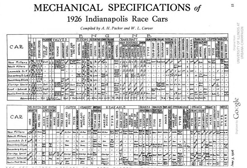
Inside Views of What Made the Wheels Go Round
High Speed 91.5 Cubic Inch Race Cars Get First Severe Test on American Tracks and Show Possibilities for Future Development
By A. H. PACKER
THE marvel of the high-speed small engine was demonstrated when the finish of the 1926 speedway contest at Indianapolis saw thirteen American built cars cross the finish line, the winner making a lower average speed than last year but outdistancing and outlasting the competitors from across the water where small-bore engines were first exploited.
Some may wonder how it is that an engine but three-quarters the size of those used last year could develop nearly the horsepower, but it is merely a case of turning up faster so that more charges of gas are fired per second in order to compensate for the reduction in fuel in each explosion.
Of those that finished, five were new Miller cars built similar to those of last year but with bore and stroke of 2.18 in. and 3 in. instead of 2.34 in. and 3.5 in. Seven of the cars were rebuilt Millers where the use of new crankshafts and special pistons made it possible to use the old cylinder blocks and one car was a new Duesenberg finished at the last minute. Six of the rebuilt Millers had bore and stroke of 2.34 in. by 2.65 in. while one driven by Thane Houser had bore and stroke of 2.188 in. and 3.00 in.
Reduction in speed compared with last year is doubtless due to the fact that this is the first year in which the small engines have been used and to the fact that the 1400 lb. chassis of last year was specified for these cars. The loss of the front wheel drive Millers from the contest while the race was still young may also have had the effect of reducing competition and permitting the drivers to use some caution in negotiating the turns on the slippery track. While the small engines proved themselves, they also brought out engineering facts that show precautions to be taken in construction of such engines for high speed and great power. The development of Fred Duesenberg’s two cycle car was partly due to his fear of the result of valves functioning with an engine turning up nearly 7,000 r.p.m. His opinion was justified in the success of his two-cycle car, which was well in the running until a blown tire caused it to skid into the wall.
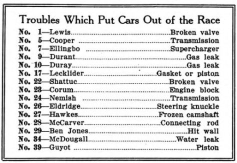
The terrific punishment that the valves and pistons get was also shown in the cars which went out. This accounted for Dave Lewis taking the count after he had turned lap after lap with uncanny precision, negotiating the turns with great ease.
The same fate overtook Shattuc driving car No. 22 earlier in the race, while engine trouble which may have been due to valves or pistons overtook Fred Lecklider, driving car No. 17.
In designing the small cylinder blocks for these cars, it was necessary to bring the valves and piston heads very close together so that in some of the practice spins it was found that the valves would actually strike the piston. A curious result of the inertia forces acting in high-speed engines was observed in some of Fred Duesenberg’s experiments preliminary to the race, when he found that duralumin connecting rods would actually increase in length, so that with pistons fitted with little clearance there was the possibility of elongated rods producing interference.
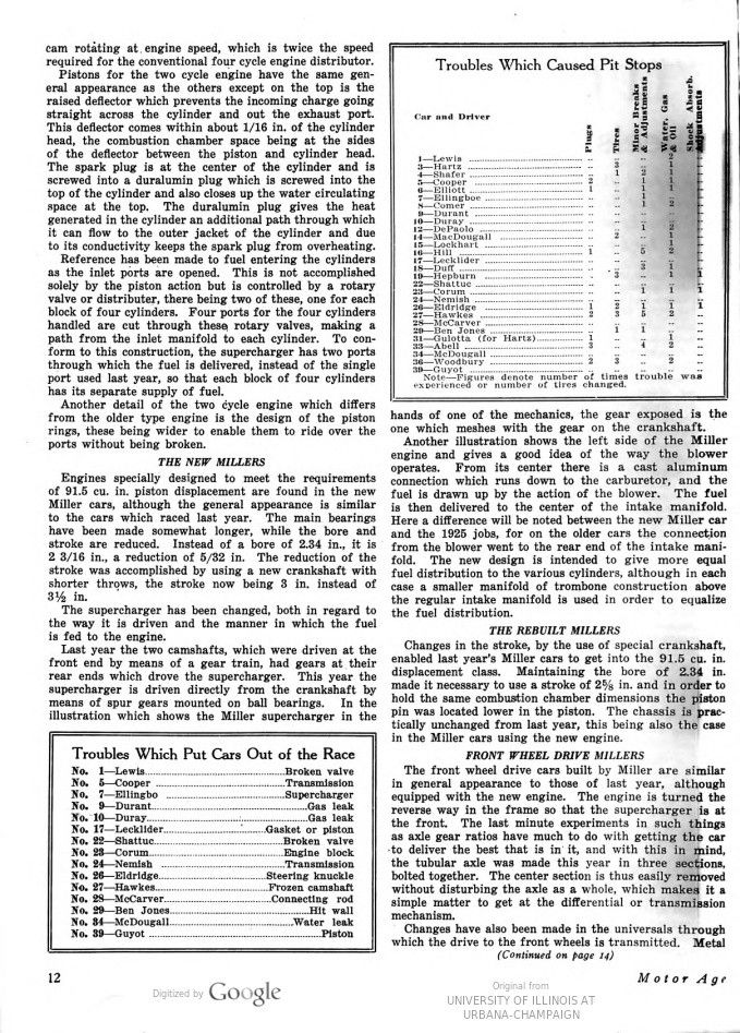
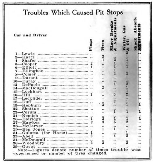
Minor troubles in many cases caused serious loss of time at the pits and in other cases put the cars out of the running. Fouled plugs were among the first troubles to cause the cars to come limping in for assistance. Loose pistons fitted for operation at excessive temperatures were to blame, indicating the need of studying the expansion problem.
Next came the problem of connections. A water leak stopped one of the English entries while the temperature indicator plug working out of McDougall’s car caused it to loose so much water that it had to be withdrawn, due to overheating. Oil lines also came in for their share of grief. In Shafer’s car No. 4 an oil connection came loose and an emergency repair was effected by using an Alemite connection for a plug. Lacking the right material and the ingenuity to use it, this car might also have been among those absent when the checkered flag was waved.
Among the list of minor ailments which proved serious were leaks in the gas tanks, which developed in the Locomobile Junior Eights entered by Clif Durant. Pit stops were also made to adjust carburetors, change tires, add water, gasoline and oil, adjust shock absorbers, adjust oil pressure and to lower air pressure in the front tires. The reduction in tire pressure was doubtless made to facilitate holding on the curves, the 30 by 5.25 balloon tires being used on nearly all of the cars.
The Hamlin front drive car built by Chevrolet Brothers made a very creditable showing in its endeavor to keep up with the eight cylinder speed creations, until one of the standard Ford connecting rods let go and put it out of the running.
Superchargers were a matter of course and no cars attempted to compete in the 500-mile grind without them. One failure of the supercharger gears was recorded, this occurring in Ellingboe’s car, while trouble with supercharger was partially responsible for the Sievers, Jr., special failing to quality in time to enter. The supercharger, properly designed, and constructed is accepted as an essential part of the modern race car and may in the near future find its way in some form into the construction of engines used for commercial purposes.
Balloon tires again demonstrated their ability to stand the grind of a long race as well as to provide comfort in passenger car service. Eighteen tires were changed as compared with 36 a year ago, but the race was shorter and the day cooler. Following is a description of the various makes of cars competing in this year’s race.
The regular Duesenberg cars differ but little, except in engine size, from those which won at Indianapolis in 1925 and 1924. The chassis is practically unchanged.
In the engine, only such changes have been made as were required by the specified piston displacement of 91½ cu. in. instead of 122 cu. in. In making such small parts it was decided there was no room available to make the heads detachable, so the engines this year have cylinder heads made integral with the blocks, the arrangement of four to a block being retained.
Several varieties of gears drive the supercharger, which is somewhat different from the previous one, although still of the centrifugal blower type, rotating approximately five times as fast as the engine crankshaft. At the front of the engine, spur gears are used, while bevel gears carry the drive to a cross shaft between the fourth and fifth cylinder. Then planetary gears are used for the final drive of the rotor. An overrunning clutch is provided to relieve the supercharger of undue stresses which would otherwise be set up when sudden changes in engine speed occur.
THE DUESENBERG TWO CYCLE ENGINE
The two cycle Duesenberg was designed to take advantage of the supercharger to the fullest extent. Previously, two cycle engines, while theoretically capable of burning the fuel twice as fast and developing twice as much power, suffered on account of a number of things. One was the difficulty of getting the old gas out which resulted in the new charge of fuel being diluted. It was also difficult to get an adequate charge in the cylinder, aside from the dilution problem.
With the supercharger, both of these difficulties are to a great extent overcome. As the piston in the Duesenberg two-cycle engine nears the bottom of its stroke, the exhaust port is uncovered. Just a fraction of a revolution later the inlet is opened and fuel under pressure is blown into the combustion chamber, driving the old gas out and filling the cylinder to capacity. The upward stroke of the piston then gives the necessary compression to develop full power.
It is interesting to think of an eight-cylinder engine firing four cylinders per revolution, but it is more interesting to think of a two-cycle construction in which eight cylinders fire every revolution, two of them firing simultaneously. First No. 1 and No. 8 fire, then No. 4 and No. 5, then No. 2 and No. 7, followed by No. 3 and No. 6.
This firing order necessitates special ignition, there being two distributors, each of which has a four-cylinder cam rotating at engine speed, which is twice the speed required for the conventional four-cycle engine distributor.
Pistons for the two-cycle engine have the same general appearance as the others except on the top is the raised deflector which prevents the incoming charge going straight across the cylinder and out the exhaust port. This deflector comes within about 1/16 in. of the cylinder head, the combustion chamber space being at the sides of the deflector between the piston and cylinder head. The spark plug is at the center of the cylinder and is screwed into a duralumin plug which is screwed into the top of the cylinder and also closes up the water circulating space at the top. The duralumin plug gives the heat generated in the cylinder an additional path through which it can flow to the outer jacket of the cylinder and due to its conductivity keeps the spark plug from overheating.
Reference has been made to fuel entering the cylinders as the inlet ports are opened. This is not accomplished solely by the piston action but is controlled by a rotary valve or distributer, there being two of these, one for each block of four cylinders. Four ports for the four cylinders handled are cut through these rotary valves, making a path from the inlet manifold to each cylinder. To conform to this construction, the supercharger has two ports through which the fuel is delivered, instead of the single port used last year, so that each block of four cylinders has its separate supply of fuel. Another detail of the two-cycle engine which differs from the older type engine is the design of the piston rings, these being wider to enable them to ride over the ports without being broken.
THE NEW MILLERS
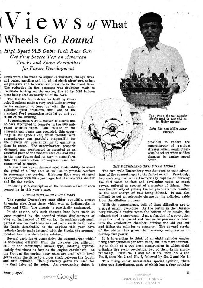
Engines specially designed to meet the requirements of 91.5 cu. in. piston displacement are found in the new Miller cars, although the general appearance is similar to the cars which raced last year. The main bearings have been made somewhat longer, while the bore and stroke are reduced. Instead of a bore of 2.34 in., it is 2 3/16 in., a reduction of 5/32 in. The reduction of the stroke was accomplished by using a new crankshaft with shorter throws, the stroke now being 3 in. instead of 3½ in.
The supercharger has been changed, both in regard to the way it is driven and the manner in which the fuel is fed to the engine. Last year the two camshafts, which were driven at the front end by means of a gear train, had gears at their rear ends which drove the supercharger. This year the supercharger is driven directly from the crankshaft by means of spur gears mounted on ball bearings. In the hands of one of the mechanics, the gear exposed is the one which meshes with the gear on the crankshaft.
Another illustration shows the left side of the Miller engine and gives a good idea of the way the blower operates. From its center there is a cast aluminum connection which runs down to the carburetor, and the fuel is drawn up by the action of the blower. The fuel is then delivered to the center of the intake manifold. Here a difference will be noted between the new Miller car and the 1925 jobs, for on the older cars the connection from the blower went to the rear end of the intake manifold. The new design is intended to give more equal fuel distribution to the various cylinders, although in each case a smaller manifold of trombone construction above the regular intake manifold is used in order to equalize the fuel distribution.
THE REBUILT MILLERS
Changes in the stroke, by the use of special crankshaft, enabled last year’s Miller cars to get into the 91.5 cu. in. Maintaining the bore of 2.34 in. displacement class. made it necessary to use a stroke of 2 5/8 in. and in order to hold the same combustion chamber dimensions the piston pin was located lower in the piston. The chassis is practically unchanged from last year, this being also the case in the Miller cars using the new engine.
FRONT WHEEL DRIVE MILLERS
The front wheel drive cars built by Miller are similar in general appearance to those of last year, although equipped with the new engine. The engine is turned the reverse way in the frame so that the supercharger is at the front. The last minute experiments in such things as axle gear ratios have much to do with getting the car to deliver the best that is in it, and with this in mind, the tubular axle was made this year in three sections, bolted together. The center section is thus easily removed without disturbing the axle as a whole, which makes it a simple matter to get at the differential or transmission mechanism. Changes have also been made in the universals through which the drive to the front wheels is transmitted. Metal joints are used and the outer ones use ball bearings on the universal joint pins, which greatly facilitates proper handling of the car on the turns
THE NICKLE PLATE SPECIAL
The two stroke cycle idea is incorporated in a rebuilt Miller engine known as the Nickle Plate Special, there being ports in the cylinder walls which are uncovered as the piston reaches the lower part of its stroke. Regulation valve action is used at the top of each cylinder to take care of the incoming gas charge, which under the pressure of the supercharger blows the old gas out. Further motion of the piston shuts off the exhaust port openings and the supercharger then fills up the cylinder.
K&M SPECIAL
The K and M Special is the product of two St. Louis men, J. J. Kellogg and E. P. Mertes. It is a four-cylinder engine of 2.585 in. bore and 4.3125 in. stroke. The crankshaft has three main bearings, the front and rear being ball and the center plain. Thermosyphon cooling is used which is unusual in race cars intended for the Indianapolis track. Gasoline to the carburetor is supplied by means of a single Autopulse unit.
The supercharger on this engine is particularly well designed and installed. It is at the front of the engine, immediately behind the radiator and is driven from the crankshaft by means of gears. The front-end camshaft drive is by means of spur gears mounted on ball bearings.
HAMLIN FRONT DRIVE SPECIAL
The Hamlin Front Drive Special was built by Chevrolet Brothers and contains a great number of Ford parts. A Ford engine with standard transmission and clutch is used, it being reversed in the car so that the transmission is immediately behind the radiator. Rods from the pedal members on the transmission run back to pedals in the driver’s cockpit, so that ideal seating conditions are obtained.
The control used in the Ford has been retained, except that the brakes are reversed, the pedal control actuating the brakes on the rear wheels, which are the new Ford type, while the lever operates the regulation transmission brake.
Ford rear springs are used both at the front and rear. The front axle which carries the differential has a short pinion shaft carried on two ball bearings and this shaft engages with the square hole into which the square shaft of the universal joint would fit on a standard Ford car.
The engine is supported at three points, the rear support being at a cross member in about the center of the car, made from a standard front cross member. The engine slopes down two or three inches at the rear, so that oil from the front or transmission end will flow back to the pump.
Pressure lubrication to all parts is used, but there is no scavenging pump as in many of the race cars, a large sump being used instead, and the oil runs into this and is recirculated by the gear type pump.
The engine has a bore of 2 7/8 in. obtained by cutting out the Ford block and putting in sleeves 3/16 in. thick, which give adequate cooling due to the uniform wall thickness. The stroke is 3½ in. A standard 16 valve Fronty-Ford cylinder head is used and a Rootes type supercharger is installed at the rear of the engine and is driven by gears from the crankshaft.
THE LOCOMOBILE JUNIOR EIGHT
Durant’s two entries, the Locomobile Junior Eights, are powered with eight-cylinder engines having bore and stroke of 3 3/16 in. and 3 in. respectively. These cars, according to Cliff Durant, have been built under the direction of Harlan Fengler. They are supercharger equipped, the drive being by means of gears at the rear of the crankshaft.
The supercharger is between the carburetor and intake manifold as it is on other cars this year, the fuel being fed to the center of the intake manifold.
GUYOT AND SCHMIDT SPECIALS
The Guyot and Schmidt specials are of unusual interest due to the use of the type of single-sleeved engine employed, and also due to the fact that rights to this construction were recently secured by the Continental Motors Corp.
The Schmidt sleeves originally had extra ports which were intended to facilitate exhausting the gas when the piston reached the bottom of the stroke. Trouble was experienced, however, due to the rings catching on the edges of the ports. For this reason special sleeves were made before the race so that to all intents and purposes the Guyot and Schmidt cars are duplicates.
THE ELDRIDGE SPECIALS
These two cars are about the same in general construction although one is wider than the other. The one with the wide frame has the oil tank at the side of the driver in the position the mechanic would occupy. The engine is four-cylinder, has rollers at main and connecting rod bearings and is provided with a Rootes type supercharger. Other details were given in the April 8 issue of MOTOR AGE.
Photos.
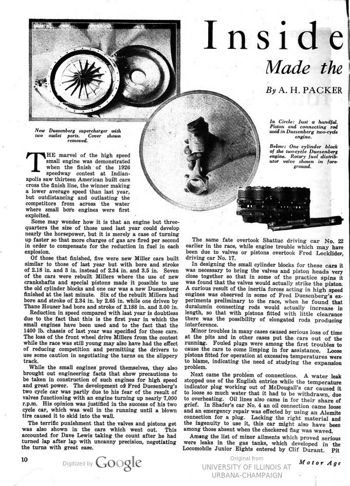
Page 10. New Duesenberg supercharger with two outlet ports. Cover shown removed.
In Circle: Just a handful. Piston and connecting rod used in Duesenberg two-cycle engine.
Below: One cylinder block of the two-cycle Duesenberg engine. Rotary fuel distributor valve shown in foreground.
Page 11. Top: One of the two cylinder blocks used in new 91.5 cu. in. Miller engines. Left: The new Miller supercharger.
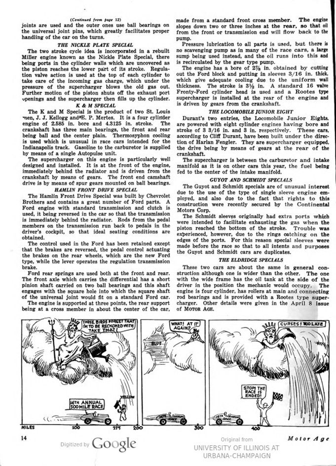
Page 14. 14TH ANNUAL 500 MILE RACE – THESE BIRDS FORGET THAT IM TO BE RECKONED WITH: TAKE THAT! – WHAT! AT IT AGAIN? – CURSES! TOO LATE – STOP!
THE RACE IS ENDED!
Page 13. June 3, 1926
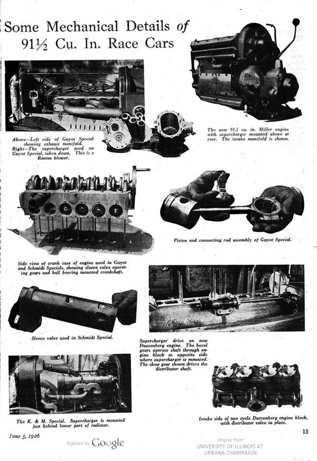
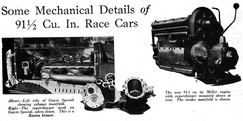
Some Mechanical Details of 9112 Cu. In. Race Cars
Above – left side of Guyot Special showing exhaust manifold.
Right – The supercharger used on Guyot Special, taken down. This is a Rootes blower.
The new 91.5 cu. in. Miller engine with supercharger mounted above at rear. The intake manifold is shown.
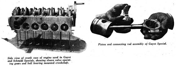
Side view of crank case of engine used in Guyot and Schmidt Specials, showing sleeve valve operating gears and ball bearing mounted crankshaft.
Piston and connecting rod assembly of Guyot Special.
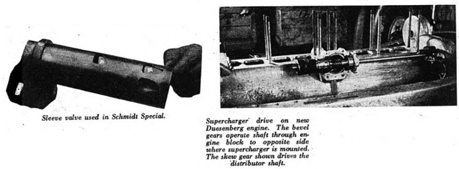
Sleeve valve used in Schmidt Special.
Supercharger drive on new Duesenberg engine. The bevel gears operate shaft through engine block to opposite side where supercharger is mounted. The skew gear shown drives the distributor shaft.
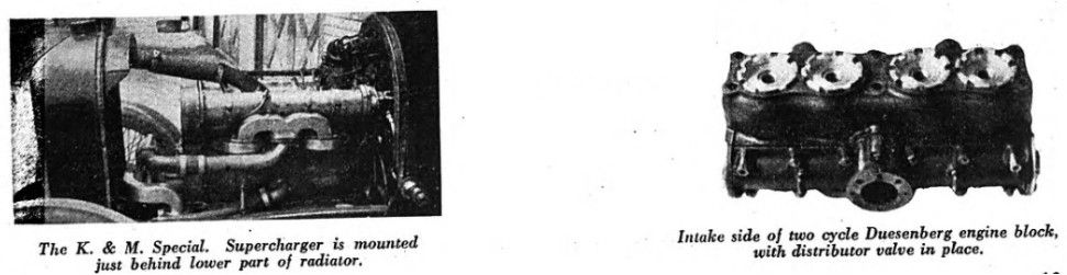
The K. & M. Special. Supercharger is mounted just behind lower part of radiator.
Intake side of two cycle Duesenberg engine block, with distributor valve in place.