


This September 1928 issue of the Journal of the SAE, deals with the up-to-then status of front wheel drive. In all, this very lenghty article comprises of no less that 25 pages, inclusive photograhs. All aspects are discussed; davantages and disadvantages are listed and compared. Almost all known front wheel drives in the US and on the continent are described. As for it’s length, the complete article is divided into four parts; here’s part III, wishing You an interesting read.


Text and jpegs by courtesy of hathitrust.org www.hathitrust.org, compiled by motorracinghistory.com
Journal of the SAE, Vol. XXIII (23), No. 3, September 1928.
Front-Wheel Drives, Are They Coming or Going? – Part III
By HERBERT CHASE – M.S.A.E.-Engineer, Erickson Co., Inc., New York City.
SEMI-ANNUAL MEETING PAPER Illustrated with PHOTOGRAPHS AND DRAWINGS
ADVANTAGES PROBABLY OUTWEIGH DISADVANTAGES
Before preparing this paper, I was inclined to think that the disadvantages of the front-wheel drive outweigh the advantages, when compared with the conventional rear-drive design, but the more I study front-wheel-drive design, the more inclined have I become to believe that the reverse is true. The number of advantages listed is greater than the number of disadvantages, and I think the advantages are also rather more important. This is largely a matter of opinion, and I have no quarrel with those who hold the contrary view. My opinion has been formulated entirely from a paper study of existing design, as I have had no actual experience with front-wheel drives. With one or two notable exceptions, however, these conclusions seem to coincide closely with those expressed by several other engineers who have made some study of front-wheel design, and most of whom have had practical experience with such designs.
FRONT-WHEEL-DRIVE TYPES COMPARED
Having studied the pros and cons of front-wheel drive design in general, a brief discussion of the various types concerning which I have been able to collect more or less information perhaps will be helpful to those who are not already familiar with the present status of the subject. A large portion of the particulars given herein necessarily has been taken from published descriptions, but I believe that several of the designs presented have not been described in American publications and that some have not hitherto been published. All these designs will be considered under Classes 1 to 3, as already stated.
SPECIFIC EXAMPLES OF CLASS 1
In the Bollstrom truck, shown in Fig. 1, the front axle resembles one form of rear axle except that steering-knuckles with universal driveshafts are provided. In this case there is an internal-gear reduction inside the wheel. This and the central housing with its differential and primary reduction-gearing add to the unsprung weight, but they present a rugged type of construction apparently well suited to truck applications. (See Automotive Industries, March 10, 1921, p. 546). **
Although the Coleman truck is a four-wheel-drive vehicle, the front axle is more or less typical of designs in Class 1. As shown in Figs. 2, 3 and 4, however, only one universal-unit is employed in each wheel. This is an unusually large universal-joint with the yoke bearings on a diameter almost equal to that of the wheel itself. The steering-knuckle pivot is at the center of the wheel and in the same plane as the universal-joint bearings. This involves the use of wheel bearings of very large diameter, and is a heavy construction which adds considerably to the unsprung weight, but it seems well suited to the heavy trucking service for which it is designed. Apparently, it does not permit a very large steering-angle, but it has the advantage of placing the universal-joint pivots at such a large diameter that the bearing pressures on them are relatively low.
Another example of a design falling in Class 1 is one of the few French front-wheel-drive cars, known as the Bucciali, in which, according to Omnia, a French periodical, the front axle is connected to the engine by a short universal-shaft. The axle center is similar to those used in conventional rear axles. The entire front-axle assembly is unsprung. The car is in very limited production. Details concerning its construction are lacking but, according to the article by P. M. Heldt, the engine, clutch and transmission form a unit. (See Automotive Industries, June 4, 1927, p. 831).
As shown in Fig. 5, the front springs are of the semi-elliptic cantilever type and are arranged at an angle to the longitudinal axis of the chassis. The rear ends of the springs extend through slots in the web of the frame channels, the center mountings being just outside this channel as shown. The springs are jointed to the trumpet-shaped axle tubes at their forward ends. Universal-joints are said to be „enclosed in the steering- knuckles in the usual way.“
DESIGNS TYPICAL OF CLASS 2
In Class 2 is included what is perhaps the best-known American front-wheel drive for passenger-cars; namely, that used on the Miller racing-car and shown in Fig. 6. The steering-knuckles are pivoted to a tubular carrying member which is bow-shaped in plan view and passes around the front of the car. To this front axle are welded shackles which are attached to four short quarter-elliptic springs, two on each side of the chassis, and arranged so that two are above and two below the axle. With this construction the unsprung weight is not much greater than that of a conventional front axle. Although the outer universal-joint adds somewhat to the unsprung weight, the brake-drums are not on the wheels but are carried on the chassis at each side of the differential; hence, there is an offsetting gain on this score. This is a Ruckstell axle which incorporates either two or three gear reductions inside the axle housing itself, that is, one casing houses both differential and transmission gears. These are carried on the chassis frame, and their weight therefore is sprung.
This same type of Ruckstell axle is used also in the new Marmon racing-car design, views of which are shown in Figs. 7, 8, and 9. The universal-joints employed in Marmon cars are of the Weiss design, shown in Figs. 10 and 11. This universal-joint possesses the peculiar advantage of transmitting a uniform angular motion between two shafts set at an angle to each other, which is not true of universal-joints of the conventional type. The yokes do not carry pins and bushings, as in the conventional type, but bear upon steel balls resting in suitable grooves cut in the yokes themselves. Because this joint transmits uniform angular motion, it is particularly well adapted for use in a front-wheel drive. The joints also take up a certain amount of end motion through the rolling of the balls in their raceways; hence, under certain conditions, no square or splined slip-joint is required, and a rolling contact is substituted for sliding contact.
In the Marmon design the front end of the engine is bolted directly to the differential case, and the gearset itself does not increase the over-all length of the assembly. The radiator is placed immediately above the differential housing. With this arrangement applied to a conventional chassis, neither the wheelbase nor the over-all length would be materially increased as compared with a conventional rear drive.
DESIGN OF THE WALTER TRUCK
In the Walter truck we have another embodiment of Class-2 design in which the differential is mounted on the frame and the two steering-knuckle pivots are connected by a rigid carrying-member, as shown in Fig. 12. In this case the axle center is designed more nearly like a conventional front-axle and is placed underneath the differential housing. Two gear-reductions are used, the second one being inside the wheel. This makes it possible to place the transverse universal-joint shaft well above the center of the wheel and makes the torque which this shaft and universal must transmit less than if the total reduction were made at the differential. The universal-joint shafts run at a slower speed than that of the crankshaft, due to the primary reduction between the bevel-drive pinion and gear, but at a higher speed than the wheels.
As compared with a hollow axle carrying a differential, the Walter form of construction seems to have some advantages on the score of less unsprung weight, despite the fact that an internal gear and pinion must be carried inside each wheel. A similar axle is used at the rear of this truck, but no steering-knuckles are provided because steering is done by the front wheels only.
FRENCH TRACTA DESIGN
One of the few and recent French front-wheel-drive designs is that known as the Tracta, shown in Fig. 13. It has individually sprung front wheels with knuckle-pivots connected by two horizontal tubes, one above and one below the center line of the wheels. These tubes are a part of the sprung weight. The total unsprung weight is made up of the wheels, outer universal-joints, steering-knuckles, and live-axle ends. Fig. 14 shows details of the universal-joints and their housing. This joint seems to be a double type and is said to transmit a uniform angular motion between the two shafts which it connects. The springs are of helical form enclosed within the cylindrical housing above the steering- knuckle pivot. On the whole this seems to be a clean design which is worthy of close study.
THE KAMM, A GERMAN DESIGN
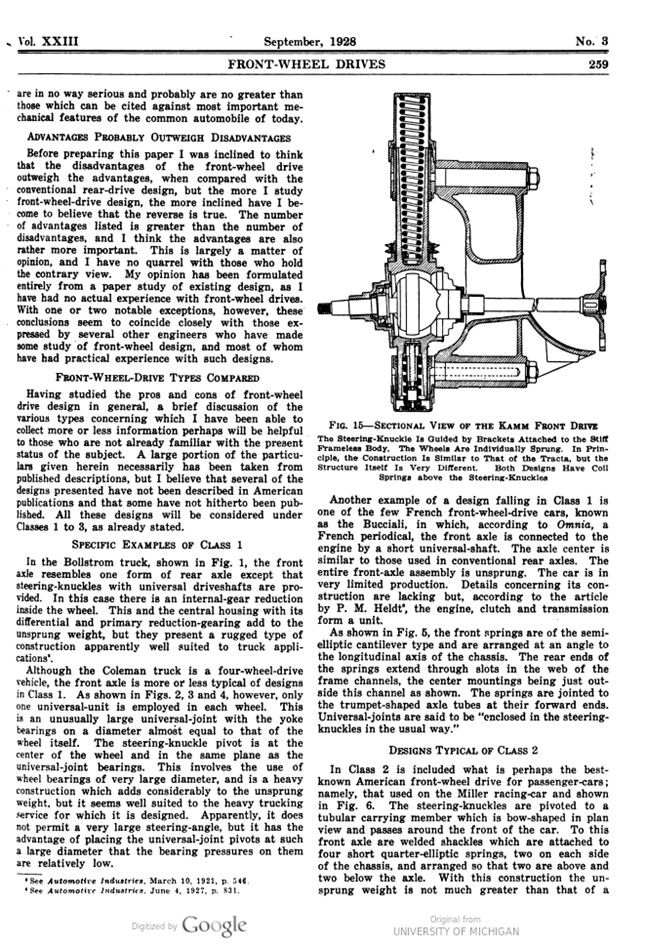
A German front-wheel-drive car described by Mr. Heldt (See Automotive Industries, June 4, 1927, p. 831) is that known as the Kamm, in which the body itself serves as a frame and also provides the guides for the mounting of independently sprung front and rear wheels. Fig. 15 shows a sectional view of the front-wheel supporting bracket and the front-wheel drive. The suspension is by a long-coiled spring above the steering-knuckle, with a shorter helical spring below. The two universal-joints at each side of the differential case are of the fabric type, but the two inside the wheels are of all-metal construction and are enclosed in a spherical housing. The universal-yoke bearing-axes lie in the same plane as that of the knuckle-pivot axis. The short spindle-shaft is supported in a single ball-bearing and is keyed to the wheel hub, which latter is supported in a ball-bearing mounted on the outside of the spindle.
CLASS 3 TYPES WITH NO DEAD AXLE
The Class-3 types without the dead axle seem to me to be the most promising of all front-wheel-drive designs for passenger-cars, and interesting details regarding American, British, Italian, French and German designs are illustrated herewith.
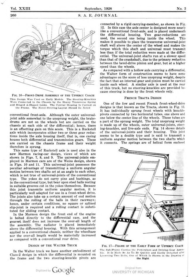
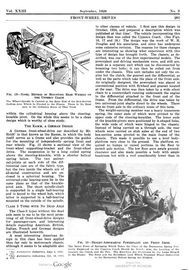
A most interesting American design in this class has been applied thus far only to motorcoach chassis, although it seems to be adaptable also to other classes of vehicle. I first saw this design in October 1924, and prepared a description which was published at that time (See Automotive Industries, Oct. 16. 1924. p. 678). The vehicle incorporating this design then was called the Uppercu Coach. (See Figs. 16, 17 and 18.) The design was the work of W. H. Douglas and his associates, and since has undergone some extensive revision. The reasons for these changes are interesting as showing what experience with this type of design has brought forth. The chassis, as described, was one of the first experimental models. The powerplant and driving mechanism were, and still are, made as a separate unit which can be disconnected by loosening two bolts; it can then be rolled out from under the chassis. This unit includes not only the engine but the clutch, the gearset and the differential, as well as the parts which take the place of the front axle. As originally designed, the powerplant was placed in conventional position with flywheel and gearset located at the rear. The drive was then taken by a wide silent chain to a countershaft running underneath the engine to the differential attached to the front end of the frame. From the differential, the drive was taken by two universal-joint shafts direct to the wheels. There was no front axle in the ordinary sense of this term.
The weight-carrying member was a heavy transverse spring, the outer ends of which were pivoted to the upper ends of the steering-knuckles. The lower ends of the knuckle-pivots were positioned by A-shaped links, the wide ends of which were hinged to the chassis. Instead of being carried on a through axle, the rear wheels were carried on stub axles at the end of two box-section arms pivoted to the main frame of the chassis. This made it possible to use a level body-platform very close to the ground. The platform re- quired no bumps or raised portions in the floor to permit axle motion. The low floor gave ample ground- clearance and also made possible a body with ample headroom but with a roof considerably lower than in conventional body-designs. Quick detachment of the complete powerplant and driving mechanism made it easy to substitute spare units and thus keep a fleet of vehicles in continuous productive operation without the loss of time ordinarily occasioned by periodic repairs.
In the Uppercu Coach design the front wheels could be turned to an angle of 53 deg., and a chassis of 220-in. wheelbase could be turned around in a 50-ft. street without backing. The actual turning-radius was 28 ft.
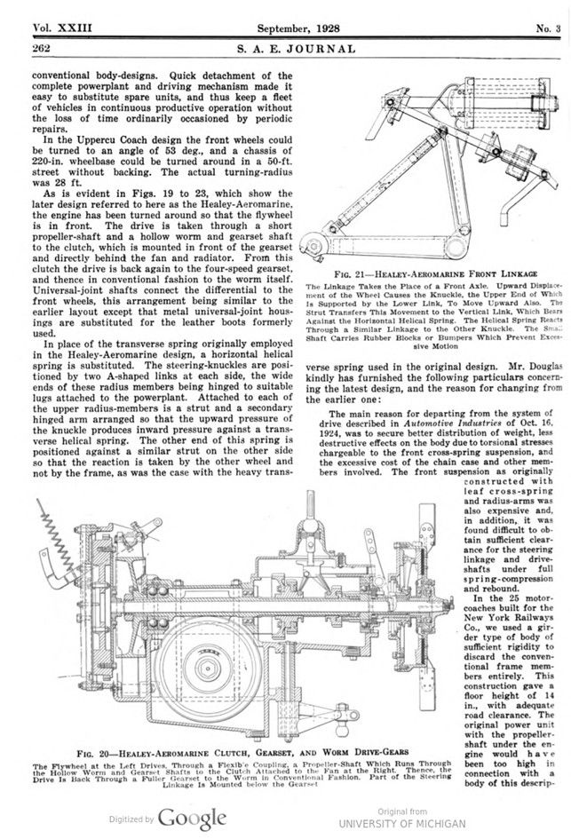
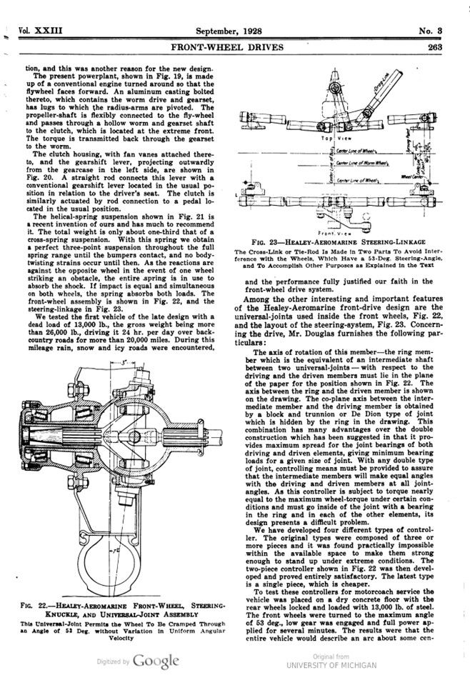
As is evident in Figs. 19 to 23, which show the later design referred to here as the Healey-Aeromarine, the engine has been turned around so that the flywheel is in front. The drive is taken through a short propeller-shaft and a hollow worm and gearset shaft to the clutch, which is mounted in front of the gearset and directly behind the fan and radiator. From this clutch the drive is back again to the four-speed gearset, and thence in conventional fashion to the worm itself. Universal-joint shafts connect the differential to the front wheels, this arrangement being similar to the earlier layout except that metal universal-joint housings are substituted for the leather boots formerly used.
In place of the transverse spring originally employed in the Healey-Aeromarine design, a horizontal helical spring is substituted. The steering-knuckles are positioned by two A-shaped links at each side, the wide ends of these radius members being hinged to suitable lugs attached to the powerplant. Attached to each of the upper radius-members is a strut and a secondary hinged arm arranged so that the upward pressure of the knuckle produces inward pressure against a transverse helical spring. The other end of this spring is positioned against a similar strut on the other side so that the reaction is taken by the other wheel and not by the frame, as was the case with the heavy transverse spring used in the original design. Mr. Douglas kindly has furnished the following particulars concerning the latest design, and the reason for changing from the earlier one:
The main reason for departing from the system of drive described in Automotive Industries of Oct. 16, 1924, was to secure better distribution of weight, less destructive effects on the body due to torsional stresses chargeable to the front cross-spring suspension, and the excessive cost of the chain case and other members involved. The front suspension as originally constructed with leaf cross-spring and radius-arms was also expensive and, in addition, it was found difficult to obtain sufficient clearance for the steering linkage and drive-shafts under full spring-compression and rebound.
In the 25 motor-coaches built for the New York Railways Co., we used a girder type of body of sufficient rigidity to discard the conventional frame members entirely. This construction gave a floor height of 14 in., with adequate road clearance. The original power unit with the propeller-shaft under the engine would have been too high in connection with a body of this description, and this was another reason for the new design.
The present powerplant, shown in Fig. 19, is made up of a conventional engine turned around so that the flywheel faces forward. An aluminum casting bolted thereto, which contains the worm drive and gearset, has lugs to which the radius-arms are pivoted. The propeller-shaft is flexibly connected to the fly-wheel and passes through a hollow worm and gearset shaft to the clutch, which is located at the extreme front. The torque is transmitted back through the gearset to the worm.
The clutch housing, with fan vanes attached thereto, and the gearshift lever, projecting outwardly from the gearcase in the left side, are shown in Fig. 20. A straight rod connects this lever with a conventional gearshift lever located in the usual position in relation to the driver’s seat. The clutch is similarly actuated by rod connection to a pedal located in the usual position.
The helical-spring suspension shown in Fig. 21 is a recent invention of ours and has much to recommend it. The total weight is only about one-third that of a cross-spring suspension. With this spring we obtain a perfect three-point suspension throughout the full spring range until the bumpers contact, and no body-twisting strains occur until then. As the reactions are against the opposite wheel in the event of one wheel striking an obstacle, the entire spring is in use to absorb the shock. If impact is equal and simultaneous on both wheels, the spring absorbs both loads. The front-wheel assembly is shown in Fig. 22, and the steering-linkage in Fig. 23.
We tested the first vehicle of the late design with a dead load of 13,000 lb., the gross weight being more than 26,000 lb., driving it 24 hr. per day over back-country roads for more than 20,000 miles. During this mileage rain, snow and icy roads were encountered, and the performance fully justified our faith in the front-wheel drive system.
Among the other interesting and important features of the Healey-Aeromarine front-drive design are the universal-joints used inside the front wheels, Fig. 22, and the layout of the steering-system, Fig. 23. Concerning the drive, Mr. Douglas furnishes the following particulars:
The axis of rotation of this member-the ring member which is the equivalent of an intermediate shaft between two universal-joints with respect to the driving and the driven members must lie in the plane of the paper for the position shown in Fig. 22. The axis between the ring and the driven member is shown on the drawing. The co-plane axis between the intermediate member and the driving member is obtained by a block and trunnion or De Dion type of joint which is hidden by the ring in the drawing. This combination has many advantages over the double construction which has been suggested in that it provides maximum spread for the joint bearings of both driving and driven elements, giving minimum bearing loads for a given size of joint. With any double type of joint, controlling means must be provided to assure that the intermediate members will make equal angles with the driving and driven members at all joint angles. As this controller is subject to torque nearly equal to the maximum wheel-torque under certain conditions and must go inside of the joint with a bearing in the ring and in each of the other elements, its design presents a difficult problem.
We have developed four different types of controller. The original types were composed of three or more pieces, and it was found practically impossible within the available space to make them strong enough to stand up under extreme conditions. The two-piece controller shown in Fig. 22 was then developed and proved entirely satisfactory. The latest type is a single piece, which is cheaper. To test these controllers for motorcoach service the vehicle was placed on a dry concrete floor with the rear wheels locked and loaded with 13,000 lb. of steel. The front wheels were turned to the maximum angle of 53 deg., low gear was engaged and full power ap- plied for several minutes. The results were that the entire vehicle would describe an arc about some center located within the rear-wheel tread and wear off about ½ in. of the front tires. We made this test several times with an old set of front tires before putting the vehicle through 20,000 miles of road testing.