


Text and jpegs by courtesy of hathitrust.org www.hathitrust.org, compiled by motorracinghistory.com
Motor Age, Vol. XXXIX (39), No. 21, May 26 1921
Straight-8 Race Engine Popular
Duesenbergs, Ballot, Sunbeam and Frontenac Exponents of This Type-Flywheel May Be Dispensed with-Better Acceleration
By B. M. IKERT
BEFORE taking up the discussion of the modern racing engine it is well to stop for a moment and see just what the first two or three major problems of the designers of this type of engine are. In the first place the designer’s job is to get the greatest amount of horsepower out of a set of cylinders of a given dimension. Everything must be done in order to insure that every ounce of energy of the fuel be utilized in turning over the engine and ultimately delivering this energy in the propulsion of the car, and the faster this propulsion takes place the more the chances the car has of winning a race, other things being equal.
The designer of a racing engine does not care very much about silence of operation. This is of no importance. Here the problem is manifestly different from that of a passenger car engine. Except to a certain extent weight is of no great importance and fuel consumption is. secondary, although obviously it does become an important factor at times. Many a race has been lost because a car had to stop for fuel at a critical period.
Vibration is not important except if it becomes so bad that trouble is likely to ensue. In a sense the design of the modern racing engine is directly opposite to that of an aircraft engine, where the size of the cylinders does not matter, but where the weight per horsepower must be kept to the lowest possible point. Fuel consumption in an aircraft engine also is important.
LARGE CRANKSHAFT FOR HIGH SPEEDS
It hardly has to be told here that the power obtained from a set of cylinders of a given dimension increases with the revolutions. This is true up to the speed at which it is practical to run the engine. It is not advisable to run an engine over a certain speed, because if this is done it means that the weight per horsepower increases. This is necessarily so because an engine that runs at excessive speeds over sustained periods requires a very large crankshaft, large bearings, and other parts to take the inertia forces. It readily will be seen, therefore, that the weight of the engine is going to mount rapidly.
If we compare a modern racing car engine with an aircraft engine, we find something like the following: The aircraft engine will have cylinders of large diameter, a medium sized crankshaft, camshaft, crankcase, etc., and will usually run at its best around speeds of from 1300 to 2000 r. p. m. The race car engine, of the high efficiency type, will have relatively small cylinders, a huge crankshaft, etc., and may be run anywhere from 2400 to 3600 r.p. m.
As yet there has been no work done along the lines of developing a straight-eight engine, one in which the cylinders are mounted in a row, for aircraft work, but the last two years have seen a remarkable growth in the development of this type of engine for racing car use. One of its salient features is the fact that it practically can be balanced perfectly. This, of course, is not true of the four- cylinder engine, which up to the last two years has had the upper hand in racing and which incidentally won last year’s Indianapolis race.
CRANK THROWS ON STRAIGHT-EIGHT ENGINE
Many do not understand fully the disposition of the crank throws straight-eight engine and to throw additional light on the subject we show in connection with this article two illustrations of crankshafts as used in eight cylinder engines. At the present time there are two arrangements of the crankshafts which seem to give the best performance and insure perfect balance.
In the Duesenberg eights which made a creditable showing last year, the crank throws are arranged as though two four-cylinder crankshafts were placed end to end and one of them given a twist so that its throws are at 90 deg. to the throws of the other. In fact the shaft is forged with the throws in a single plane, after which the shaft is given a quarter twist.
The other way of arranging the throws is assuming an ordinary four-cylinder shaft with half of another four-cylinder shaft placed at each of its ends, each of these halves being placed at right angles to it. This is the better arrangement, as the shaft then is balanced, whereas in the former case we have the equivalent of two unbalanced four-cylinder crankshafts. Such an engine necessarily will set up a rocking moment between the two sets of four cylinders.
When it comes to mechanical efficiency it is doubtful whether the straight-eight engine possesses any advantages over the four-cylinder. Some engineers claim that the straight-eight will absorb more power in friction than the four-cylinder or the six, owing to the relatively larger number of small bearings as compared with a few larger ones in the other engines. This also brings up the question of dependability.
Theoretically at least it is right to assume that a four-cylinder engine will be more suitable than the straight-eight for racing, because when we multiply the number of wearing parts as is the case in the eight we naturally run the chances of having just so many more parts misfunctioning. However, in many of the races that were run last year the straight eight certainly demonstrated that it was a very reliable engine. Therefore, it is doubtful in the minds of many whether or not the four-cylinder is more reliable for racing than the straight-eight.
There will be a large number of both types in the race at Indianapolis this year and the results of their relative performance will be interesting to watch. Some of the more prominent users of the straight eight at Indianapolis are Sunbeam, Ballot, Duesenberg, Talbot-Darracq and one or two others. Most prominent among the fours are the Frontenacs and Peugeot.
TRYS ALUMINUM FOR RACING ENGINES
Concerning the last two makes of engines there is a bit of history which is interesting because out of it all has come the development of the aluminum engine as exemplified by that used for the last five years by Louis Chevrolet in his famous Frontenac cars. Along about in 1915 Chevrolet, who had had up to that time considerable racing experience and who had watched the progress in racing made by Peugeot, knew that the engines of the Peugeot type had been developed to their highest efficiency and in order to beat them some other course must be pursued by the designers of race cars. It would not do to merely equal their performance; it must be surpassed. So, Chevrolet turned to aluminum.
By the wide use of aluminum, Chevrolet was able to use a 300 cu. in. aluminum engine and chassis which complete weighed 500 lb. less than any similar car. Naturally this light weight did not mean so much in the way of speed increase as it did in the saving of tires and, therefore, a reduction in the number of stops during a long race. We show a cross-sectional view of the early Frontenac engine.
Some of the steel parts which made up this engine weighed considerably more than the main body of the engine, such as the cylinder, water jackets, and crankcase. The crankshaft weight was 92 lb. and the flywheel, clutch, cone bearings 140 lb. The connecting rods collectively weighed 7 lb., the fore pistons 3 and the carbureter 10 lb. By using an engine of this kind, it was possible to reduce the weight of the rear axle to 200 lb., whereas the average axle may run as high as 400 lb.
In the early Frontenac engine the cylinder walls did not come in contact with the pistons, but instead cast iron sleeves or liners of thin section were inserted into the cylinder bores to take the wear. These were inserted from the bottom of the bores and held in place by friction.
They were introduced while the cylinders were at a high temperature obtained by steam in the water jackets. They were, therefore, automatically clamped in place at normal temperatures when the cooling water was in the jacket instead of the steam. As the temperature on the inside of the cast iron sleeve rose so much higher than that of the water-cooled aluminum which surrounded them, the cast iron sleeves expanded and tightened up inside of the aluminum rather than the aluminum expanding away from the sleeves.
It will be noted from the end section of the Frontenac engine that the seats for the valves are made up from iron castings with dove tailed edges and cast in the aluminum. This made the cast iron seats independent. The difference of the expansion of the cast iron and the aluminum did not affect the alignment of the adjacent cylinders.
This engine had a bore of 3.87 in. and stroke 6.37 which made it just under 300 cu. in. Chevrolet claimed that this engine was capable of developing between 135 and 140 hp. with 105 lb. per sq. in. compression pressure. The intake valves were made lighter and larger in diameter than the exhaust valves. In the valve operating mechanism a very short spring was placed inside of the main spring which made it possible to get the valve returned to its seat very quickly. The wide difference in the length of these two springs made it possible to dampen out any vibration which either one or the other of the springs might have had when running at a „critical“ speed.
In order to use the ball bearings on the crankshaft it was necessary to make the shaft up in two pieces joined at the middle. It was held together by one large through bolt and three smaller ones. At the points where these smaller bolts passed the division on the crankshaft hardened steel bushings closely fitted were used to take the torque. They acted like keys and relieved the bolts of driving stresses.
PISTONS COOLED BY LARGE AIR BREATHERS
The early Frontenac engine used a single overhead camshaft driven by means of beveled gears instead of a train of spur gears as used in the Frontenacs of last year. The first Frontenac engines also had a train of three spur gears to drive the water and oil pump and the magneto. The spur driving and the beveled gears are attached to the front end of the crankshaft and made from a single piece to add strength and reduce weight.
The Frontenac engines of last year differed quite a bit from the early engines, particularly that two camshafts were used and a train of spur gears in place of the bevel gears and vertical shaft for driving the valve mechanism. Two oiling systems are used on this engine, one mechanical and the other manual. The latter is for emergencies only. Both are of the dry sump type, the oil being carried in an 8 gal. tank on the car and circulated by a two stage gear pump.
One of the interesting features is the cooling of the pistons. It was not thought desirable to dissipate the heat through the cylinder walls and water jackets because the wall area necessary in this case is so great as to make the pistons too heavy to travel at the required rate of speed. The designers of this engine have found it possible to air cool the pistons which fact accounts for the very large breathers on the sides of the engine, one in front and the other in the rear. Air enters in the front breather, goes through the crankcase and out of the rear breather which has an inverted tube facing downward in a compartment separated from the crankcase proper with a port entering the chamber at the top and also one at the bottom. The breather tube in this chamber is sealed at the top and has a series of staggered holes down its side. It was designed to take as much air as possible from the crankcase and condense the oil vapor at the same time.
The crankshaft in this engine is quite heavy weighing about 165 lb. The pistons are 2½ in. long, 3 1/8 in. in diameter and have two cast iron rings % in. square. The valves in this engine have a diameter of 1 7/16 in. in the clear and a lift of 7/16 in. There are four valves per cylinder. The engine on the dynamometer delivered 86 hp. at 3200 r.p.m. This, it is said, is not as high as that obtained from some of the eight cylinder engines of the same piston displacement.
On a test under wide open throttle this engine delivered an average of 78 hp. for one hour at 3200 r.p.m. During this trial the engine had a gasoline consumption of .625 lb. per hp. hour. This same engine ran 500 miles on the Indianapolis at an average speed of 88.7 miles per hour with an average of 10 miles per gallon of gasoline.
The oil consumption in the race was very high. This was due no doubt to the arrangement of the camshaft and because the valve mechanism was exposed. The racing car engine as a general thing seems to throw a great deal of oil and this especially might be true of this type of engine where the breather is very large and the cam housing is overhead.
Photo captions.
Page 17.
End sectional view of the Frontenac engine built in 1915 by Louis Chevrolet. This shows the iron liner in the aluminum cylinder block and also the cast iron valve seats
Page 18.
Sectional Views of Engines Designed for Speed
Longitudinal sectional views of the early and late Frontenac engines. On the left is the engine which won last year’s Indianapolis race, while the one on the right is the same as that shown on the previous page. Note that in the later engine the camshaft drive is by a series of spur gears rather than a vertical shaft and bevel gears
Crankshafts Used on Straight Eights
Two layouts for straight-eight crankshafts. The one at the top is preferable because with it the engine is balanced practically perfect.
Page 19.
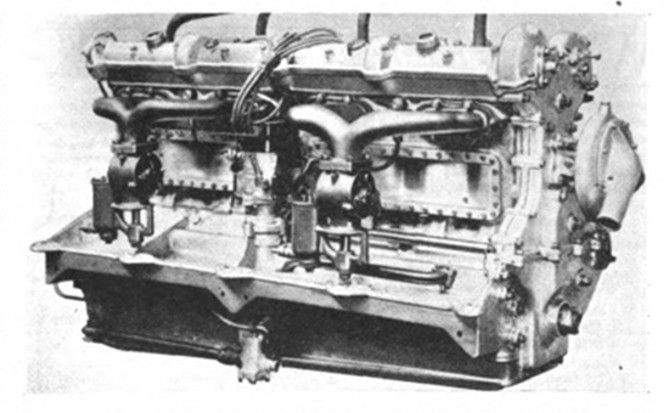
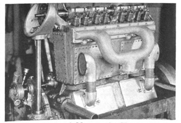
Engines Old and New to the Hoosier Oval
At the top is the engine used in the Peugeot to be driven by Chassagne and Wilcox. Note the manner of mounting this engine by means of trunnions. Below it is the eight cylinder Sunbeam engine. Instead of the two carbureters four will be used with a special form of air scoop as shown elsewhere in this issue. At the bottom is shown the Frontenac engine used in the 1915 cars. Note the large breathersm.