


Text and jpegs by courtesy of hathitrust.org www.hathitrust.org, compiled by motorracinghistory.com
Automotive Industries, Vol. XLV (45), No. 18, November 3, 1922
New Duesenberg Reflects Experience Gained with Racing Cars
Striking engineering features characterize the latest product. An eight-in-line engine, four-wheel brakes, overhead camshaft, and tubular connecting rods are included in design. High pressure oiling is employed. Drive shaft and front axle are tubular. Semi-elliptic springs used.
By J. Edward Schipper
INCORPORATING such features as an eight-in-line engine, hydraulically operated four-wheel brakes, overhead camshaft, tubular connecting rods and a weight of only 3200 lb. in spite of a wheelbase length of 134 in., the new Duesenberg presents some very interesting engineering features. This car is one of the most direct interpretations of racing experience which has ever been offered to the public. Its engine is identical in many respects with the 183 cu. in. engine of the Duesenberg racer which recently won the French Grand Prix race. With a bore of 2 7/8 in. and a stroke of 5 in., it has a displacement of 260 cu. in. and develops from 90 to 100 hp. An output of 1 hp. per 2.6 cu. in. of piston displacement with a compression of 80 lb. per square inch gage gives a good idea of the characteristics of the engine. The upper half of the crankcase and the cylinder block containing the eight barrels are cast as a unit. The cylinder head is removable and incorporates the overhead camshaft and rocker arms. The valve and spring mechanism are inclosed by a detachable cover plate and the lower half of the crankcase and the oil pan are a unit aluminum casting, removable while the engine is in the frame.
The pistons are magnalite, although cast iron will be supplied if desired. They are of flat-top design, 3% in. in length, with three 1-in. rings. The tubular connecting rods are 934 in. in length, machined all over and equipped with annular cooling ribs at the lower end. The piston pin is held in the upper end of the connecting rod by a lock screw, the bearing being held in the piston.
Three main bearings support the one-piece crankshaft. The crankshaft diameter is 2% in. at all main bearings, and the bearing lengths are 22, 22 and 3 in., front, center and rear. The lower connecting rod bearings are all 2 in. by 1% in. It has been found that the use of a smaller diameter at the end of the throw than at the main bearing is a material factor in assisting balance of the crankshaft. Spiral bevel gears and a vertical shaft are used for driving the one-piece, hollow camshaft which is mounted on five bearings. There are two valves per cylinder, each actuated by a forged alloy steel rocker arm, and two concentric springs. The valves open downward directly into the spherical combustion chamber, which is polished to prevent carbon collection. The vertical drive shaft is made in two pieces so that the head can be removed and replaced without changing the valve timing, the driving lug on the vertical shaft being offset so that the head can be replaced in only one way.
High-pressure oiling is employed, the oil pump being Forward part of Duesenberg eight-In-line chassis driven directly from the crankshaft. This is a gear pump capable of delivering a maximum pressure of 250 lb. per square inch. The oil is led through the drilled crankshaft to all of the main bearings under pressure and also to the hollow camshaft and hollow rocker arm shaft. The pressure feed, therefore, is directly to the camshaft bearings and also to the rockershaft bearings, from which the oil feeds to the valve driving contact points. The mechanism underneath the valve cover plate is really operating in an oil mist, due to the high pressure employed and the large supply of oil forced into the head by the oil pump. The oil return passes over the camshaft driving gears, keeping these supplied with a bath of oil. The breather pipe is on the left rear end of the engine and has a hinged cap. It acts as the oil filling passage, and upon the front of the breather pipe is the oil level indicator gage.
The water pump is a centrifugal impeller type driven by a cross-shaft which receives its drive from the vertical camshaft drive shaft. The cross-shaft terminates at the water pump on the right and on the left delivers the drive through a set of bevel gears to the auxiliary shaft. The fan pulley is in front of the bevel gearcase and behind it the drive is transmitted through a flexible coupling to the generator and distributor, the latter being mounted on the rear end of the generator. An interesting feature in connection with the cooling system is that the water enters the block at the lower right in front and leaves it at a point just above the point of entry. The circulation is controlled by internal baffles.
Gasoline is fed from a 20-gal. tank located at the rear of the chassis to a Stewart vacuum tank mounted on the dash. The 12-in. Stromberg carbureter is located on the right side of the engine, the gas flow being vertically upward to a hot-spot contact with the exhaust manifold, which is located on this side of the block. From this point the gas is taken through a straight passage between the two center cylinders across the block to the left side of the engine, where it enters the aluminum intake manifold, which is of ramshorn design. This distribution system for the gases is clearly shown in the left-side view of the engine herewith.
Suspension System
The flywheel is a steel forging, machined all over, with the starting gears cut in the periphery. The clutch is housed in the flywheel, which latter is inclosed in a bell housing which carries the side arms for two points of the engine suspension system. The third point of suspension is at the front end, where there is a patented trunnion, giving a three-point flexible mounting. The clutch is a single dry plate type and the gearset a three- speed unit, providing ratios in the gearbox of 4.016 to 1 on reverse, 3.167 to 1 on first, and 1.1654 to 1 on second. The rear axle ratio is 4.6 to 1. The drive to the rear axle is through a double flexible joint and a tubular drive shaft, which is inclosed in a torque tube. The thrust of propulsion is also taken on this torque tube, which carries a yoke at its forward end hinged to the center cross-member of the frame. In addition, there are two radius rods which run from the extremities of the rear axle to the front end of the torque tube. The rear axle housing is of molybdenum steel, in one piece, and reinforced. The pinion shaft is mounted on two double-row annular ball bearings. The differential consists of a forged steel case inclosing the spider arm, four bevel gears and two side gears splined for the axle shaft. The hollow axle shaft is of molybdenum steel, the shaft and hub being in one piece. The wheels are Rudge-Whitworth design and are mounted on annular ball bearings.
The front axle is also tubular and the axle ends and steering knuckles are of molybdenum steel. The front axle, which is shown in section herewith, is claimed to be more than 25 per cent lighter than the usual type of front axle and at the same time more than 25 per cent stronger. The axle is so designed as to incorporate the passages for the brake operating fluid.
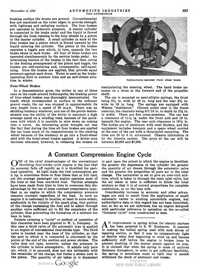
The brake drums are forgings 16 in. in diameter and are fitted to all four wheels. In order to obtain a perfect braking surface the drums are ground. Circumferential fins are machined on the outer edges to provide strength. with lightness and radiating surface. The four brakes are operated by hydraulic pressure. A master cylinder is connected to the brake pedal and the liquid is forced through the lines running to the four wheels by a piston in the master cylinder. A small cylinder in each of the four brakes has a piston which is forced upward by the liquid entering the cylinder. The piston at the brakes operates a toggle arm which, in turn, expands the two brake shoes in each brake. All four of these brakes are operated simultaneously by the service brake pedal. An interesting feature of the brakes is the fact that, owing to the floating arrangement of the piston and toggle, the brakes are self-centering and, consequently, self-equalizing. Once the brakes are applied, they provide equal pressure against each drum. Water is used as the brake-operating fluid in summertime and an anti-freeze solution in winter.
Four-Wheel Brakes.
In a demonstration given the writer in one of these cars on the roads around Indianapolis, the braking power of four-wheel brakes was thoroughly demonstrated. On roads which corresponded in surface to the ordinary gravel roads, the car was stopped in approximately its own length from a speed of 30 m.p.h. There was no skidding tendency whatever, and one of the points demonstrated was the ability of the driver to maintain a high average speed on a winding road, because of the quickness with which it is possible to slow down on coming into a curve. An interesting point brought out was the fact that during the time all four brakes are applied the car loses much of its responsiveness to the steering wheel because of the tendency to go into a front-wheel skid with the front-wheel brakes applied. A driver soon becomes educated, however, to releasing the brakes on manipulating the steering wheel. The hand brake operates on a drum at the forward end of the propeller shaft.
The car is mounted on semi-elliptic springs, the front being 24 in. wide by 40 in. long and the rear 2½ in. wide by 59 in. long. The springs are equipped with Watson „stabilators.“ Chrome nickel steel is the frame material, the channels being 6-7/16 in. in depth by 2 1/8 in. in width. There are five cross-members. The car has a clearance of 11½ in. under the front axle and 10 in. beneath the engine. The rear axle clearance is 10½ in. The bodies are of aluminum with steel fenders, and the equipment includes bumpers and a spare wheel carried at the rear of the car with a three-point mounting. The tires are 33 by 5 in. all-around. Chassis lubrication is by the Alemite system. The price of the car will be between $6,000 and $7,000.
Photo captions.
Page 855.
Duesenberg eight-cylinder-in-line engine
Details of front and rear axles and hydraulically-operated brakes
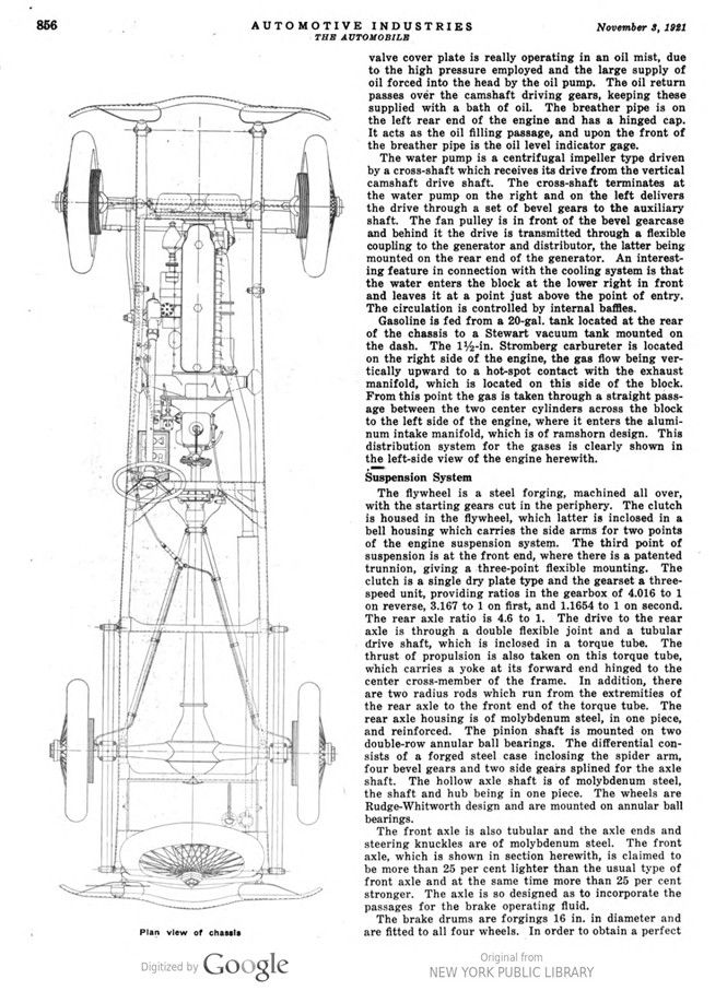
Page 856. Plan view of chassis
Page 857. Hydraulically-operated front wheel brake