


This article from the well-known French technicalist-journalist Charles Faroux describes the 1912 newly designed steel detachable wheel of the company Rudge-Whithworth. Here, it says like: „….a new wheel hub assembly…..which not only provides absolute security against loosening, but also tightens itself during operation if it has been insufficiently tightened during assembly“. Part of this article is more like a conversation between author and reader; have to get acquainted with this kind of discussing a technical item, but it’s very explaining.
With authorisation of Conservatoire numérique des Arts et Métiers (Cnum) – https://cnum.cnam.fr
Text and photos compiled by motorracinghistory.com, translation by DeepL.com
La Vie Automobile Volume 10. — N° 576. – Saturday october 12, 1912.
The new removable wheel RUDGE-WITHWORTH model 1913
Our readers are familiar with the many successes achieved by Rudge-Whitworth metal wheels in all the races that have taken place over the past several years. It seemed that the locking device designed by the company’s engineers, having been crowned with victory so many times, would continue to enjoy a long career. But that would be to misunderstand the R. W. management, to assume that they would be content to rest on their laurels after so many triumphs, because now they are launching a new removable wheel that is wonderfully simple and even disconcerting at first glance, but which, given the ingenuity of its design and the reputation of the company that created it, is destined to be a great success and cause a sensation.
Before discussing the locking mechanism, and in order to fully understand its usefulness and how it works, let’s look at the problem.
To allow for easy assembly and disassembly of a removable wheel, it has an outer hub that can be fitted with a smooth friction fit onto a fixed hub permanently attached to the spindle. Once in place, the outer hub must be secured to the fixed hub in all directions in order to receive the driving and braking forces from it, and to prevent any play that would quickly destroy the strength of the assembly. Finally, and of the utmost importance from a safety point of view, once assembled, the two hubs must not be able to separate except by the will of the driver, and neither shocks nor road vibrations must have any influence on them. Finally, disassembly and reassembly must be easy, and the locking system must make these maneuvers easy.
We know how these various conditions were achieved on the Rudge-Whitworth wheel. The wheel hub was driven by the fixed hub—and still is in the new wheel—by means of fine splines cut with a milling cutter on the outer surface of the fixed hub, which engage with similar splines on the inner surface of the wheel hub. The two hubs are centered on each other by means of a conical surface C, inclined at 30° to the axis, on which the wheel hub, equipped with a similar surface, rests.
Once the wheel hub is in place on the fixed hub, in all removable wheel systems it is held in place by a nut that presses it firmly onto the conical part, thus keeping it exactly centered.
The problem posed by the detachable wheel is simply to prevent this nut from loosening unless force is applied to it using a special wrench. It should be noted that in the old Rudge-Whitworth wheel, this nut was locked in place by means of a double locking mechanism.
An automatic lock, consisting of a ratchet that a spring constantly pushed into a gear carried by the fixed hub and inclined in the direction of screwing so as to allow tightening and prevent loosening; and a safety lock, operated by hand, which could only function when the previous ratchet was properly in place. It must be acknowledged that this system offered perfect safety at the cost of very little complexity, and that if R.W. wheels came loose, it could only have been as a result of inconceivable and almost criminal negligence on the part of the person using them.
Now, Rudge-Whitworth is introducing a new wheel hub assembly on the fixed hub, as shown in our illustrations, which not only provides absolute security against loosening, but also tightens itself during operation if it has been insufficiently tightened during assembly.
So how is this new system constructed? Our illustrations show it’s simplicity. The wheel has a wheel hub M (fig. 1) which is mounted on the fixed hub N, where splines D are used to drive it. A conical stop C is used to center the two hubs on each other, and a ring A, threaded on the inside, screws onto a thread F carried by the fixed hub and rests on the wheel hub via a conical bearing surface H, thus firmly holding the latter centered between the two bearing surfaces H and C.
And then? That’s it. What? What about the lock? What about the automatic lock? What about the manual lock? What happened to them? They’ve been removed; there’s no lock anymore.
But everything will come loose while riding, due to the vibrations! — No, on the contrary, everything locks into place.
Here, let’s try it out. Let’s mount our wheel, screw ring A on by hand, without tightening it, and ride a kilometer.
Now check your ring: it is tightened to the max, so much so that it is impossible to loosen it without the special wrench.


My dear reader, you are somewhat bewildered by this paradoxical result, and I understand that. You have seen so far that vibrations are the worst enemies of bolts and nuts, you know all the trouble we have gone to, and still go to, to obtain a nut that will not come loose, and here is one that is so obliging that it tightens itself for no apparent reason. What is this mystery? How is this strange result achieved?
By a very simple means, which was easy to think of: ring A has a thread with a diameter slightly larger than that of the thread on the fixed hub N. And that’s all there is to it.
You still don’t understand; wait. Let’s consider, if you will, the diagram in Figure 3, which shows a ring A resting under its own weight on a shaft B, and having a larger diameter than the shaft. Let’s turn shaft B counterclockwise, for example, and assume that the surfaces of B and A are rough enough for the drive to take place. What will happen? The shaft A, in its movement, will drive the ring B. If the diameter of B is, for the sake of argument, 2/3 of that of A, when B has made one revolution, A will have made only 2/3 of a revolution. After one revolution, ring A will therefore be 1/3 of a turn behind shaft B, and it will be as if we had turned A 1/3 of a turn relative to B, which we assume to be fixed, in the opposite direction to the movement, i.e., clockwise.
If we now assume that A and B have right-hand threads, we see that A will have screwed itself 1/3 of the pitch onto shaft B.
Well, that’s the secret, and we have created the device for securing our hub. Let’s refer to Fig. 4 and examine the figure on the right. When ring A is not fully screwed in, it rests on the upper part of the thread F of hub N, leaving a certain amount of play between it and the lower part of the thread. It is therefore off-center in relation to this hub, and if we start the machine, the phenomenon we have just described will occur. With each turn, A will screw onto F by a fraction of a pitch represented by the difference in diameters, and after a certain number of turns, it will lock. At this point, the ring will be centered in relation to the hub, due to the conical bearing H of the wheel hub on which it rests. Its position is shown in the right-hand figure in Fig. 4, and the thread play occurs between the inner face of the ring thread and the outer face of the hub thread.
Of course, the thread must be oriented so that the movement of the car causes it to tighten. Since this tightening occurs as a result of the ring lagging behind the rotation of the hub, the thread must therefore turn in the opposite direction to the rotation of the wheels. The thread will be left-handed for the right wheels and right-handed for the left wheels. To unscrew the ring, remember that the wrench must turn in the same direction as the wheels when driving forward.
And when driving in reverse, you may ask? Won’t it come loose?
If the ring is locked, it will not come loose, since there is no eccentricity or movement of the ring relative to the fixed hub. Everything turns as one piece, without relative movement. If the ring is deliberately loosened, it will continue to loosen, but very slowly. You would have to walk for at least a mile for the ring to unscrew by a single turn. Who would want to loosen the ring on their wheels and then drive for miles in reverse?
Let’s not forget, moreover, that when you start driving forward again, the tightening occurs automatically: and once achieved, driving backward does not affect it in any way. Really, to lose a wheel while driving backward, you would have to want to do so with a strong determination and uncommon perseverance!
This device therefore provides a perfectly secure assembly. As for its advantages, there are many.
First of all, simplicity. A wheel hub, a fixed hub, a ring. That’s all. Nothing but revolving parts that can be made on a lathe; no fragile components, nothing that can warp or get lost, nothing that can catch, no protrusions.
As for the operating mechanism, there are no more complicated keys that are difficult to insert: just a simple pin key that fits into one of the four notches on the ring.
The operating procedure is extremely simple. Unscrew the ring by turning it in the direction of rotation of the wheel in forward gear, remove the wheel, place its replacement on the fixed hub, and lock it in place. No more locks to watch out for when reassembling, no more latches to lift when dismantling.
With the old system, it sometimes happened that after locking the wheel properly, we were surprised to find it completely unlocked after a few kilometers. This was due to gravel getting between the conical stops of the wheel hub and the fixed hub. The gravel was soon crushed by the movement of the vehicle and disappeared, leaving a gap between these two parts. Here, there is no need to worry about this, as the movement automatically tightens the wheel.
For the same reason, there is no need to periodically check the tightness of the wheels, as it is always perfect.
The fixed hub is much simpler in shape than the old one. Its mounting on various types of steering or drive axle spindles is no longer a problem due to its cylindrical shape. The splines are much longer, ensuring a better connection between the two hubs.
Maintenance is also greatly reduced, since all the complications of the old locking system have disappeared. It is limited to lubricating the surfaces of the hubs that come into contact, as well as the threads of the fixed hub and the ring. That’s all. As for lubricating the ball bearings on the spindle, this is just as easy as on ordinary wheels, as there are no components in this area. Simply remove the cap E, fill it with grease, and screw it back on, unless you screw a special syringe (grocerjack: a synonym for „a device used to inject fluids into or withdraw them from something such as a cavity) in its place.
I have placed particular emphasis on the hub of this wheel and its locking device, which is its most interesting feature. As we have seen, it is not the torsional force that tightens the ring; this force is supported by the splines and the locking system is completely removed from it. The ring is only screwed on by rolling onto the end of the fixed hub, due to the effect of its weight, which gives it a certain eccentricity because of its slightly larger diameter.
It should also be noted that the tightening thus obtained can never be excessive, since it ceases as soon as centering is achieved. At this point, since the ring and the hub are concentric, no relative movement can take place. We would add that this system has undergone numerous rigorous tests over the past two years, which have been entirely satisfactory.
The wheel assembly has remained unchanged, as it was already perfect in this respect. The strength of this component has been fully demonstrated by the various tests, mainly speed races, in which it has taken part. Consider the stresses that the wheels of the Peugeot cars in Dieppe and Le Mans had to endure at speeds exceeding 180 km/h, and consider the lateral forces experienced when cornering with the skill we know they are capable of, and it becomes clear that no demonstration could be more convincing.
We know that the wheel consists of three parts: the hub, the spokes, and the rim. We have just described the hub in detail. Let us just add that it is made of high-strength stamped steel.
The spokes comprise three sets: the outer spokes R1 (fig. 5), the inner spokes R2, and the innermost spokes R3. These spokes, also made of high-strength steel, are reinforced at both ends, with the two diameters connected by a very elongated truncated cone to avoid any sudden variation in cross-section. They are tangent to a circle concentric with the hub and implanted directly in it, rather than attached to sidewalls as in bicycle wheels. The latter arrangement requires the end of the spoke to be sharply bent, which causes it to work under shear, whereas implantation in the body of the hub gives it only a slight curvature at this point.
The rim has nothing in common with the ordinary rim of a wooden wheel except its external appearance. In reality, it is much stronger. In order not to reduce its strength at the point where the spoke nut is attached and to allow the head of the nut to rest normally across its entire surface, a small boss is stamped at this point and then drilled to allow the spoke to pass through. The entire wheel is then assembled, the spokes are tensioned to the desired tension, and the whole thing is enameled in the oven.
It is easy to understand that such an assembly is both much more precise and more durable than a wooden wheel. Almost all wooden wheels are out of true when they are new, and even more so when they are worn. Here, the wheel is made to be perfectly circular and remains so indefinitely.
My readers are familiar with the advantages of metal wheels: lower moment of inertia, elasticity, better cooling, etc., which make them less demanding on tires. They know that for this reason I have a fondness for them that I make no secret of. I have often been asked the question: „You say that metal wheels wear out tires less, but what proof do you have of this? What specific experiments have been carried out? Have the two types of wheels ever been compared, all other things being equal, under identical conditions of use? Finally, are there any figures that indisputably establish the superiority of this type that you hold so dear?“ Here are the figures:
Daimler recorded the lifespan of 50 tires mounted on fixed wooden wheels and 50 tires mounted on removable RW wheels on the cars in its rental fleet. These were the same cars, performing the same service, on which the latter had been substituted for the former.
And here is the lifespan of a tire in each case:
On fixed wooden wheels 2,050 miles
On removable RW wheels 8,454 miles
This represents a 70% increase in lifespan.
Suppose that tomorrow a carburetor were launched that could travel 170 kilometers on the same amount of gasoline that used to travel 100 kilometers. How eagerly would we rush to its inventor! However, the cost of tires is higher than that of fuel. If the metal wheel had only this advantage, it would seem to me that it would become the norm.
But the new version produced by Rudge-Whitworth is so simple and safe thanks to its automatic locking mechanism, and so easy to handle when dismantling, that its adoption completely eliminates the nightmare of punctures or blowouts. What used to be a calamity in certain circumstances—urgent trips, night journeys, or travel in bad weather—is now nothing more than a minor incident, and the longest part of the whole operation is undoubtedly the maneuvering of the jack.
Designed in this way, the removable metal wheel must win everyone over.
What can be said against it? The only arguments still raised against its use are the difficulty of cleaning it and its lack of aesthetic appeal. As for the first, R.-W. has created the necessary equipment, an ingeniously designed brush that makes it easy to reach every corner of the wheel. As for the second, it was loudly proclaimed two years ago, but is less prominent today. The fact is that aesthetics are relative and people have become accustomed to it. Today’s motor car would seem a hideous machine to our grandfathers, who were accustomed to gilded, springy carriages, and in five years‘ time the wooden wheel will seem highly unattractive to us. And long before that, we will be grateful to Rudge-Whiworth for making the indispensable use of pneumatic tires more economical and less burdensome.
Charles Faroux.
Photo captions.
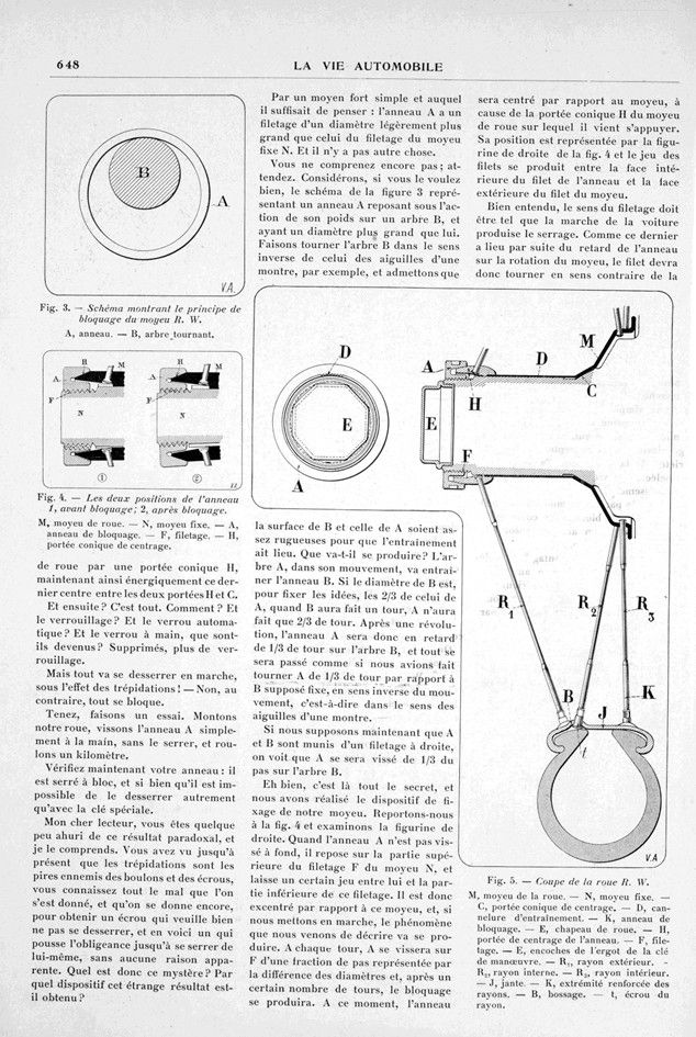
Fig. 1. — Cross-section of the new detachable hub R. W.
M, wheel hub. — N, fixed hub. — C, conical centering surface. — D, drive splines. — A, locking ring. — H, conical centering stop for the ring. — F, thread. — E, wheel cap.
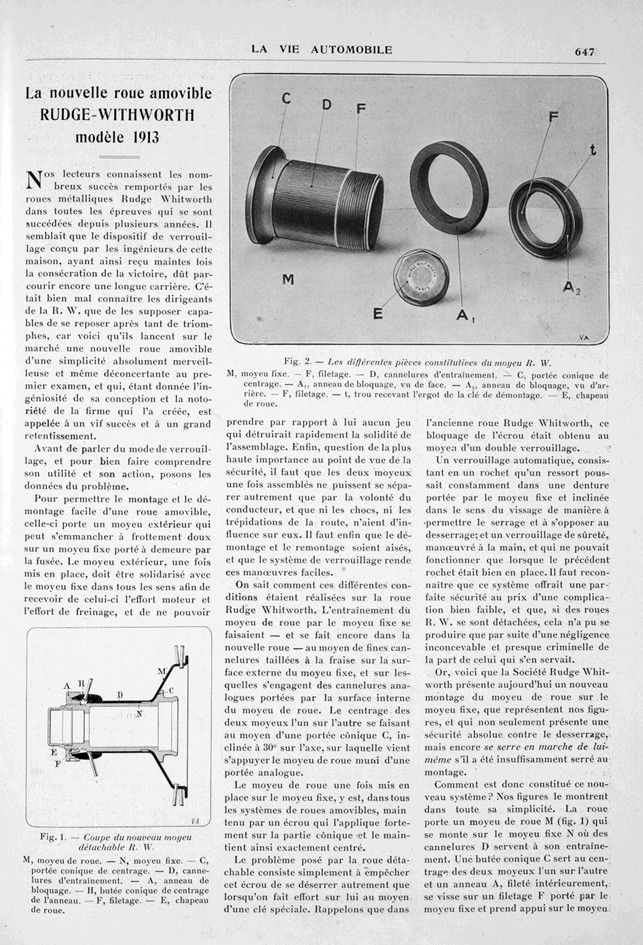
Fig. 2. — The various components of the R. W. hub.
M, fixed hub. — F, thread. — D, drive splines. — C, conical centering surface. — A, locking ring, viewed from the front. — A2, locking ring, rear view. — F, thread. — t, hole for the removal key pin. — E, wheel cap.
Fig. 3. — Diagram showing the locking principle of the R. W. hub.
A, ring. — B, rotating shaft.
Fig. 4. — The two positions of the ring 1, before locking; 2, after locking.
M, wheel hub. — N, fixed hub. — A, locking ring. — F, thread. — H, conical centering surface.
Fig. 5. — Cross-section of wheel R. W.
M, wheel hub. — N, fixed hub. — C, conical centering surface. — D, drive groove. — K, locking ring. — E, wheel cap. — H, centering surface of the ring. — F, thread. — E, notches on the pin of the operating key. — R, outer radius. -R2, inner radius. — R3, inner radius. — J, rim. — K, reinforced end of spokes. — B, boss. — t, spoke nut.
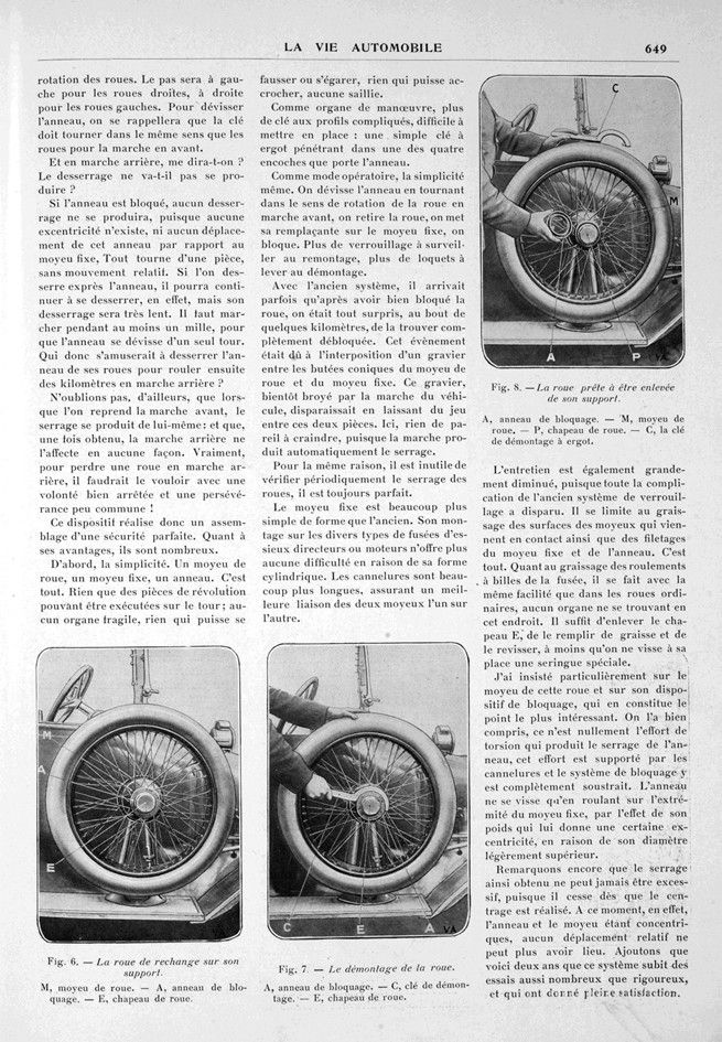
Fig. 6. — The spare wheel on its support.
M, wheel hub. — A, locking ring. — E, wheel cap.
Fig. 7. — Removing the wheel.
A, locking ring. — C, removal wrench. — E, wheel cap.
Fig. 8. — The wheel ready to be removed from its support.
A, locking ring. — M, wheel hub. — P, wheel cap. — C, removal wrench with lug.
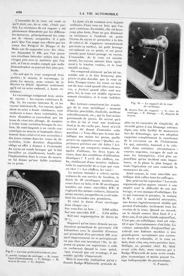
Fig. 9. — The wheel ready to be put in place.
C, conical centering surface. — D, drive splines. — F, thread. — M, wheel hub. — E, cap.
Fig. 10. — The spare wheel support.
M, smooth hub of the support. — C, centering cone. — F, thread. — E, hub cap.