


Over many years, the technical specialist and highly rated author Peter Martin Heldt wrote for several American automotive magazines. In this 1927 article in Automotive Industries, he explains the different aspects of the then upcoming front-wheel drive. Because of its lengthy write, it’s divided here in two parts. Not only an interesting read, but I find it baffling how in-depth he decsribes the many different aspects of front-wheel drive.

Text and jpegs by courtesy of hathitrust.org www.hathitrust.org, compiled by motorracinghistory.com
Automotive Industries, Vol. 56, No. 27, June 4, 1927
Impasse in Car Development May be Circumvented by FRONT WHEEL DRIVE – Part II
Will permit still further lowering of bodies and this is one reason why it may appeal to designers.
By P. M. HELDT (Engineering Editor, Automotive Industries)
SINCE the writing of this article, the prediction was made in New York by Charles Faroux editor-in-chief of La Vie Automobile, of Paris, that the next important development in automobile design will be the introduction of front wheel drive models by many passenger car manufacturers.
Experiments on front wheel drives are being made secretly at the present time by many leading European manufacturers, said M. Faroux, and as a result of this activity he expects to witness the early introduction of several new front drive cars.
M. Faroux made his prediction at a luncheon tendered him by the officers of the National Automobile Chamber of Commerce, on the eve of his return to France after a six-weeks‘ tour of American factories. – Editor.
Characteristics Different
The characteristics of this drive are rather different from those of the drive in which the power is trans- mitted to the wheel hub directly through a shaft with universal joints. For instance, when the wheels are swung around the knuckle pins, a motion is transmitted through the bevel gears to the differential side gears. The two wheels swing in the same direction, looked at from the top, and they cause the two axle shafts to turn in the same direction, looked at from opposite sides of the car. Their motions, therefore, would be compensated through the differential were it not for the fact that in making a turn, the inner wheel always deflects through a larger angle than the outer one. This extra swinging motion of one wheel as compared with the other results in rotation of the crankshaft – with the power when the wheels are being deflected, and against it when they are being returned to their normal or „straight-ahead“ position. Hence the steering will be non-uniform, requiring more effort to return the wheels than to deflect them from the straight-ahead position, and once the wheels are swung over to one side they will have a tendency to assume a position of maximum angularity.
It is well known that when brakes are applied, whether they act on front or rear wheels, some of the weight is transferred from the rear to the front wheels. In the opposite case, when the car is being accelerated some of the weight is transferred from the front to the rear wheels. This tends to increase the adherence of the driving wheels in the case of rear drive, and to decrease it in the case of front drive. To get an idea of what this transfer of weight amounts to, let us take the case of a car developing a maximum torque of 120 lb.-ft. having a total reduction in low gear of 15 to 1 and a wheelbase of 9 ft. Then, disregarding frictional losses, the maximum torque on the driving axle will be 15 × 120 1800 lb.-ft. which corresponds to a weight removed from or added to the other axle of 1800/9 = 200 lb.
This would be of the order of 10 to 12 per cent of the weight on that axle. Consequently, the ground adhesion is increased by 10 to 12 per cent in the case of rear drive and decreased an equal amount in the case of front drive, and the limiting traction will be from 18 to 20 per cent less in the case of the front drive than in that of the rear drive.
With the clutch and transmission in front of the engine, the connections to the control devices would not be quite as simple as in a conventional car, and this is a disadvantage of the front drive, but not a serious one.
In the conventional rear-drive car the reactions on the axle housing of the driving and braking torque must be provided for, as well as the propulsive thrust and the drag due to the brakes. In a front-driven car, on the other hand, if the brake is supported by the powerplant and the final reduction gears are inclosed within the housings of same, all torque reactions come directly on the latter and need not be specially provided for. The case is different if there is a gear reduction at the wheels, with the driving pinions supported in bearings on the steering heads. In that case the torque reaction will come on the latter and they must be properly supported against it.
Driving thrust and braking drag originate at the ground contact surfaces of the tires and must be taken up either through the springs or through radius rods. A word in regard to universal joints for front drives will not be amiss. Of the two universals in each drive shaft, the one near the central housing has to take care only of the angularity due to spring play. Fortunately, the vertical play of the front spring is not very great, being limited to about 2 in. to both sides of the normal position. Moreover, spring play does not affect the parallelism between the differential shafts and the knuckle shafts, and the angle between the differential shaft and the axle shaft is always the same as the angle between the axle shaft and the knuckle shaft, hence the speed fluctuations created by one joint will be neutralized by the other.
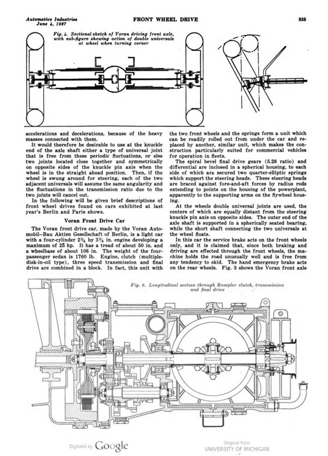
It is different, however, with respect to the angularity between shafts due to steering motion. The angle of the steering spindle with the axle may exceed 30 deg., in fact it may reach 40 deg., and for such angles there would be extreme fluctuations in the speed of the driven member if the speed of the driving member were constant. For an angle of 30 deg., for instance, the speed of the driven shaft would fluctuate through a range equal to 29 per cent of its mean speed. Actually, of course, neither the driving nor the driven shaft would run at constant speed, but one would accelerate and the other at the same time decelerate, and both would be subjected to very great stresses as a result of these accelerations and decelerations, because of the heavy masses connected with them.
It would therefore be desirable to use at the knuckle end of the axle shaft either a type of universal joint that is free from these periodic fluctuations, or else two joints located close together and symmetrically on opposite sides of the knuckle pin axis when the wheel is in the straight-ahead position. Then, if the wheel is swung around for steering, each of the two adjacent universals will assume the same angularity and the fluctuations in the transmission ratio due to the two joints will cancel out.
In the following will be given brief descriptions of front wheel drives found on cars exhibited at last year’s Berlin and Paris shows.
Voran Front Drive Car
The Voran front drive car, made by the Voran Automobil-Bau Aktien Gesellschaft of Berlin, is a light car with a four-cylinder 234 by 334 in. engine developing a maximum of 25 hp. It has a tread of about 50 in. and a wheelbase of about 106 in. The weight of the four- passenger sedan is 1760 lb. Engine, clutch (multiple- disk-in-oil type), three speed transmission and final drive are combined in a block. In fact, this unit with the two front wheels and the springs form a unit which can be readily rolled out from under the car and replaced by another, similar unit, which makes the construction particularly suited for commercial vehicles for operation in fleets.
The spiral bevel final drive gears (5.28 ratio) and differential are inclosed in a spherical housing, to each side of which are secured two quarter-elliptic springs which support the steering heads. These steering heads are braced against fore-and-aft forces by radius rods extending to points on the housing of the powerplant, apparently to the supporting arms on the flywheel housing.
At the wheels double universal joints are used, the centers of which are equally distant from the steering knuckle pin axis on opposite sides. The outer end of the axle shaft is supported in a spherically seated bearing, while the short shaft connecting the two universals at the wheel floats.
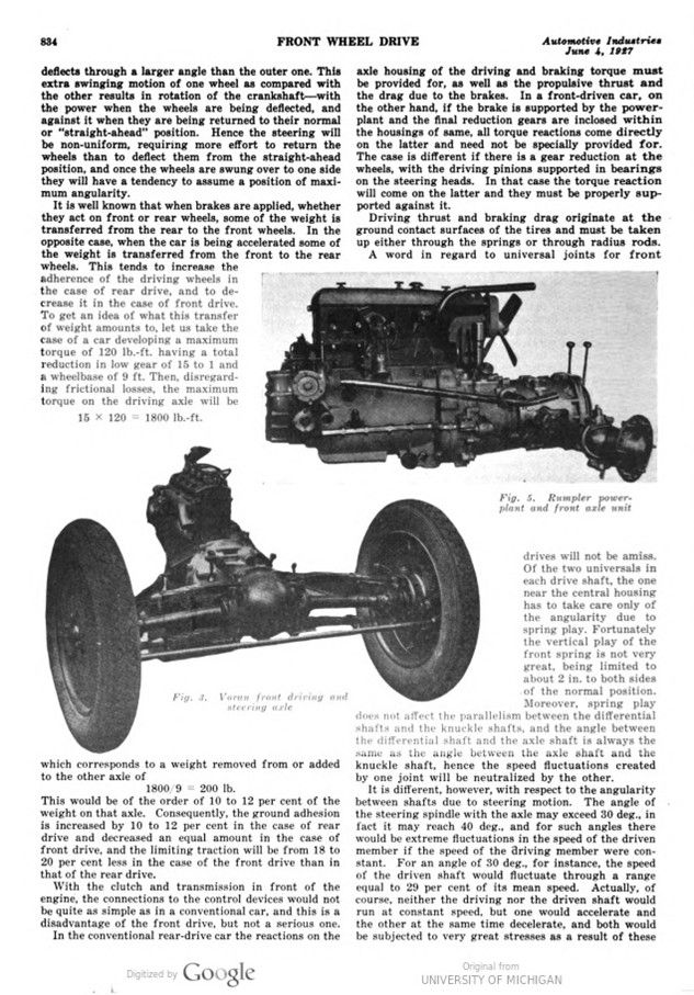
In this car the service brake acts on the front wheels only, and it is claimed that, since both braking and driving are effected through the front wheels, the machine holds the road unusually well and is free from any tendency to skid. The hand emergency brake acts on the rear wheels. Fig. 3 shows the Voran front axle while Fig. 4 is a sectional sketch showing the angular relations of the shafts in the straight-ahead position and in turning corners.
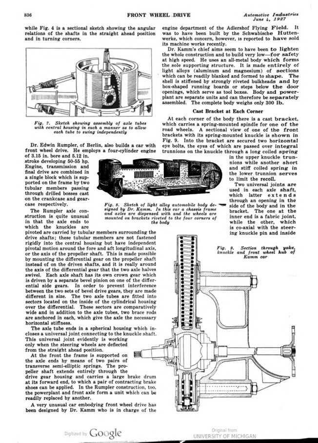
Dr. Edwin Rumpler, of Berlin, also builds a car with front wheel drive. He employs a four-cylinder engine of 3.15 in. bore and 5.12 in. stroke developing 50-55 hp. Engine, transmission and final drive are combined in a single block which is supported on the frame by two tubular members passing through drilled bosses cast on the crankcase and gear-case respectively.
The Rumpler axle construction is quite unusual in that the axle ends to which the knuckles are pivoted are carried by tubular members surrounding the drive shafts; these tubular members are not fastened rigidly into the central housing but have independent pivotal motion around the fore and aft longitudinal axis, or the axis of the propeller shaft. This is made possible by mounting the differential gear on the propeller shaft instead of on the driven shafts, and it is really around the axis of the differential gear that the two axle halves swivel. Each axle shaft has its own crown gear which is driven by a separate bevel pinion on one of the differential side gears. In order to prevent interference between the two sets of bevel drive gears, they are made different in size. The two axle tubes are fitted into sectors located on the inside of the cylindrical housing over the differential. These sectors are comparatively wide and in addition to the axle tubes, two brace rods are anchored in each, which give the axle the necessary horizontal stiffness.
The axle tube ends in a spherical housing which incloses a universal joint connecting to the knuckle shaft. This universal joint evidently is working only when the steering wheels are deflected from the straight-ahead position.
At the front the frame is supported on the axle ends by means of two pairs of transverse semi-elliptic springs. The propeller shaft extends entirely through the drive gear housing and carries a large brake drum at its forward end, to which a pair of contracting brake shoes can be applied. In the Rumpler construction, too, the powerplant and front axle form a unit which can be readily replaced by another.
A very unusual car embodying front wheel drive has been designed by Dr. Kamm who is in charge of the engine department of the Adlershof Flying Field. It was to have been built by the Schwabische Huttenwerke, which concern, however, is reported to have sold its machine works recently.
Dr. Kamm’s chief aims seem to have been to lighten the whole construction and to build very low – for safety at high speed. He uses an all-metal body which forms the sole supporting structure. It is made entirely of light alloys (aluminum and magnesium) of sections which can be readily blanked and formed to shape. The shell is stiffened by strongly riveted bulkheads and by box-shaped running boards or steps below the door openings, which serve as tool boxes. Body and powerplant are separate units and can therefore be separately assembled. The complete body weighs only 300 lb.
Cast Bracket at Each Corner
At each corner of the body there is a cast bracket, which carries a spring-mounted spindle for one of the road wheels. A sectional view of one of the front brackets with its spring-mounted knuckle is shown in Fig. 9. Into the bracket are secured two horizontal eye bolts, the eyes of which are passed over integral trunnions on the knuckle through a long-coiled spring in the upper knuckle trunnions while another short and stiff coiled spring in the lower trunnion serves to limit the recoil. Two universal joints are used in each axle shaft, which latter extends through an opening in the side of the body and in the bracket. The one at the inner end is a fabric joint, while the other, which is co-axial with the steering knuckle pin and inside the spherical housing of the knuckle, is of the metallic type. The short drive shaft inside the knuckle spindle is supported in a ball bearing mounted in the spindle and is designed to be keyed into the wheel hub which latter is supported by a ball bearing mounted on the outside of the spindle. The drive is transmitted in a very effective way through the trunnions of the knuckles.
Several front-drive cars were shown at the last Paris automobile show. In the Bucciali car the arrangement of the engine, clutch, transmission and final drive in a single unit is substantially the same as in the systems already described. A praiseworthy attempt has been made to make the appearance of the front conform to that of standard rear-driven cars. To this end the radiator is formed with a central circular notch at the bottom into which the driving gear housing fits. This gives a front elevation very similar to that of certain other French cars in which the combined generator and starter is mounted at the front of the engine and under the radiator.
In this car the front axle tubes are made of trumpet form, and they pivot around the axis of the propeller shaft or bevel gear shaft. Half-elliptic cantilever springs are used at the front. These are arranged at an angle to the longitudinal axis of the frame and extend through slots in the webs of the frame channels, the center mounting of the spring being just outside and the rear eye inside the channel. At their forward end these springs are jointed to the axle tubes. Truss rods extend from the bottom of the driving gear housing to the lower part of the axle end, to insure parallel motion of the axle ends under spring action. Universal joints are inclosed in the steering knuckles in the usual way.
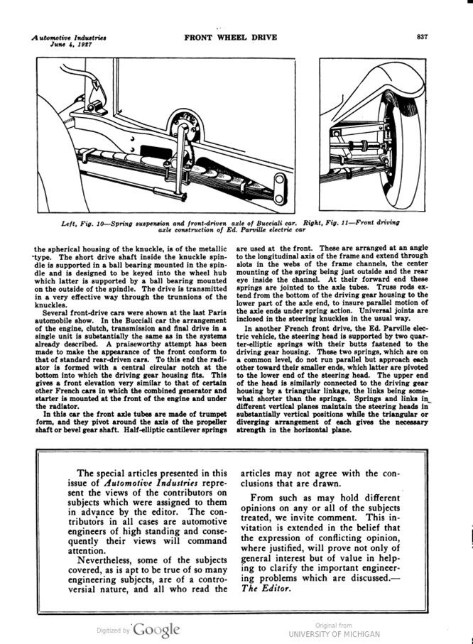
In another French front drive, the Ed. Parville electric vehicle, the steering head is supported by two quarter-elliptic springs with their butts fastened to the driving gear housing. These two springs, which are on a common level, do not run parallel but approach each other toward their smaller ends, which latter are pivoted to the lower end of the steering head. The upper end of the head is similarly connected to the driving gear housing by a triangular linkage, the links being somewhat shorter than the springs. Springs and links in different vertical planes maintain the steering heads in substantially vertical positions while the triangular or diverging arrangement of each gives the necessary strength in the horizontal plane.
Photo captions.
Page 21, Fig. 1. Miller front drive, as developed specially for racing cars
Fig. 2. Itala front drive car
Fig. 3. Voran front driving and steering axle
Fig. 4. Sectional sketch of Voran driving front axle, with sub-figure showing action of double universals at wheel when turning corner
Fig. 5. Rumpler powerplant and front axle unit
Fig. 6. Longitudinal section through Rumpler clutch, transmission and final drive
Fig. 7. Sketch showing assembly of axle tubes with central housing in such a manner as to allow each tube to swing independently
Fig. 8. Sketch of light alloy automobile body designed by Dr. Kamm. In this car a chassis frame and axles are dispensed with and the wheels are mounted on brackets riveted to the four corners of the body
Fig. 9. Section through yoke, knuckle and front wheel hub of Kamm car
Left, Fig. 10. Spring suspension and front-driven axle of Bucciali car.
Right, Fig. 11. Front driving axle construction of Ed. Parville electric car