


In this september 1895 issue of the French popular scientific magazine La Nature, the French technical journalist Baudry Saunier presents two innovations. First the wheel hub in ball bearings and secondly, the ever first Michelin pneumatic tyre as applied in the 1895 Paris-Bordeaux contest. The assembly and securing means for the tyre are extensively described. This article later was published in English in the Scientific American of december 1895.

Avec l’authorisation du Bibliothèque national francais, gallica.bnf.fr.
Text et photos compilé par motorracingistory.com. Translation by DeepL.com
La Nature, Vol. 23, No. 1162, september 7, 1895
INFLUENCE OF VELOCIPEDS ON CAR BODYWORK
BALL BEARING HUBS AND TIRES – FOR CAR WHEELS
Until recent years, horse riders considered bicycles so unworthy of their attention that they long missed out on the benefits of the wise improvements in vehicle design that bicycles had pioneered. Now that cycling has become an elegant sport, people are beginning to recognize that it is a useful, ingenious sport worthy of attention, and certain features of bicycle construction are now being tried out on heavier means of transportation.
At the last Cycle Show, at the entrance to the motor vehicle galleries, visitors could see car wheels suspended freely on their axles, which seemed to rotate indefinitely with the slightest push of the thumb! These were the first tests, carried out by Belvallette, of ball bearings for car axles.
Clearly inspired by cycling! Ball bearings have the distinction of greatly surprising the average person; it is generally believed that this device was invented for bicycles, whereas in 1857 there was already a patent for a system of ball bearings applicable to bells, millstones, threshing machines, etc., and the first person to apply ball bearings to cycling was a Mr. Suriray in 1869, who owned a sawmill in Melun whose flywheel was mounted on ball bearings!
In any case, it is certain that Mr. Belvallette, himself a veteran cyclist, improved the bearings on his cars by skillfully copying the bearings on a bicycle. A clever copy, I said, because the aim was to make a sturdy axle, whose bearings could not escape from the clumsy hands of a groom, and whose adjustment was both easy and mathematical.
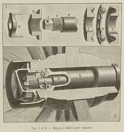
After much trial and error, Mr. Belvallette settled on the following device: the axle D shown in Figure 1 and indicated in Figure 2 as being placed in the hub K supports, at its end, a cup G with a triangular groove, which forms the counterpart of a cup A with the same profile mounted on the hub. Between the two, a washer B with holes holds the balls in place; the holes are slightly smaller in diameter than the balls. The end of the axle has a thread E and a pentagonal part F. A nut G is screwed onto the thread and held in place by a bronze lock nut IL. This lock nut, in combination with the end of the spindle and the adjusting nut, allows the tightness of this nut to be varied 30 times in a single turn, i.e., adjusted to 1/30 of a millimeter. A leather washer is also inserted between the axle washer and the box when it is in place on the axle to block the passage of oil and dust.
As can be seen, the device is simple and sturdy. Careful experiments on a coupe fitted with ball bearings, carried out using the dynamometer car of the Compagnie Générale des Voitures in Paris, have shown that the improvement in rolling resistance was approximately 30% on good road surfaces and approximately 20% on flat roads covered with snow. Even if these figures are not entirely confirmed in practice, it is nonetheless certain that ball bearings save many kilograms of effort on the part of the living machines that are horses. From the point of view of efficiency alone, the application is therefore extremely valuable.
A second and very important influence of cycling on carriage manufacturing is undoubtedly the adoption of pneumatic rubber tires. Two or three years ago, the first tests were carried out in London on the coupé of a director of a large bicycle factory in England. However, difficulties in demolding and dismantling the type of rubber chosen meant that the idea was shelved for a while. It was taken up again in France.
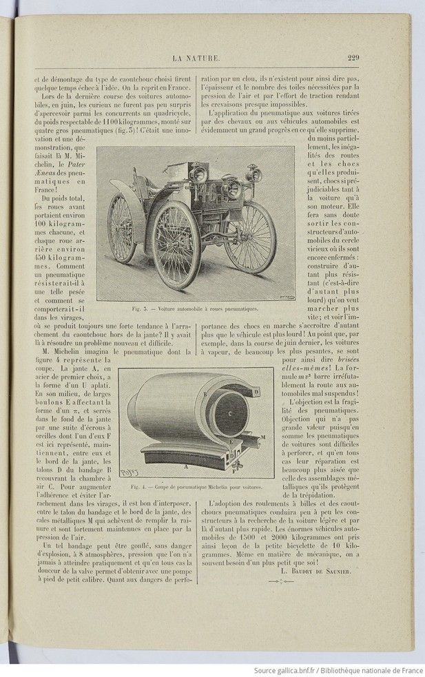
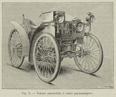
During the last car race in June, curious onlookers were not surprised to see among the competitors a quadricycle, weighing a respectable 1,100 kilograms, mounted on four large pneumatic tires (fig. 3)! It was an innovation and a demonstration by Mr. Michelin, the Pater Æneas of pneumatic tires in France!
Of the total weight, the front wheels carried about 100 kilograms each, and each rear wheel about 450 kilograms. How could a pneumatic tire withstand such a load and how would it behave in corners, where there is always a strong tendency for the rubber to be torn off the rim? There was a new and difficult problem to be solved.
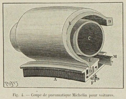
Mr. Michelin designed the tire shown in cross-section in Figure 4. The rim A, made of high-quality steel, is shaped like a flattened U. In the middle, large bolts E in the shape of a π, tightened into the bottom of the rim by a series of wing nuts, one of which (F) is shown here, hold the beads D of the tire B in place between themselves and the edge of the rim, covering the inner tube G. To increase grip and prevent tearing in corners, it is a good idea to insert, between the bead of the tire B and the inner tube G, a layer of fabric (E) that is not glued to the tire. the beads D of the tire B covering the inner tube G. To increase grip and prevent tearing when cornering, it is advisable to insert metal wedges M between the bead of the tire and the edge of the rim, which fill the groove and are held firmly in place by the air pressure.
Such a tire can be inflated to 8 atmospheres without risk of explosion, a pressure that is practically never reached and which, in any case, can be achieved with a small foot pump thanks to the smoothness of the valve. As for the danger of punctures by nails, this is virtually non-existent, as the thickness and number of plies required by the air pressure and traction force make punctures almost impossible.
The use of pneumatic tires on horse-drawn carriages or motor vehicles is obviously a great advance in that it eliminates, at least partially, the unevenness of roads and the shocks they produce, which are so damaging to both the car and its engine. It will undoubtedly free automobile manufacturers from the vicious circle in which they are still trapped: building vehicles that are more resistant (i.e., heavier) in order to go faster, only to see the impact of shocks increase as the vehicle becomes heavier! To the point that, for example, in last June’s race, the steam cars, which were by far the heaviest, virtually broke themselves! The mv2 formula irrefutably blocks the way for poorly suspended cars!
The objection is the fragility of the tires. This objection is of little value since, after all, car tires are difficult to puncture, and in any case, they are much easier to repair than the metal assemblies they protect from vibration.
The adoption of ball bearings and pneumatic tires will gradually lead manufacturers to seek lighter and therefore faster cars. The enormous 1,500- and 2,000-kilogram motor vehicles have thus learned a lesson from the small 10-kilogram bicycle. Even in mechanics, we often need something smaller than ourselves!
L. Baudry de Saunier.
Photos. Fig. 1 and 2. — Ball bearing hub for cars. Fig. 3. — Motor car with pneumatic tires. Fig. 4. — Cross-section of Michelin tire for cars.