


This article explains the 1909 Christie design, carrying an off-line position for the engine to the wheel axis, togehther with the clutch, the two-speed (and reverse) transmission, the final drive and te differential. Gear ratio in Drive is 4:1 or 8:1


Text and jpegs by courtesy of hathitrust.org www.hathitrust.org, compiled by motorracinghistory.com
The Automobile, Vol. XX (20), No. 23, August 5, 1909
Walter Christie’s Front Drive Autocab
SEEKING the unusual, one can find much of interest in the completed front-drive cab, which the manufacturer and inventor, Walter Christie, of Eleventh avenue and Twenty-third street, New York City, says is the only proper solution not alone of the complicated cab situation, but of the question of ultimate drive for all automobiles.
Mr. Christie is a versatile inventor, having to his credit the revolving turret for warships, a very efficient form of packing for steam pistons of large diameter, and other innovations. But his pet is the combination front drive and front steer, to which ignorant and unthinking ones have applied the title of „freak.“ This really is a misnomer, for it presents nothing of the odd or whimsical, as freak is defined, but, rather, contributes ideas worthy of much thought.
Not only is the new car, which is of small power, comparatively light weight and suitable primarily for taxicab use, equipped with a front drive, but the block motor shows a number of carefully worked out details, while the transmission is a masterpiece of rugged yet small and compact work. The wheels, too, designed by Christie especially for cab work, are based upon an idea which may be generally adopted before long.
All engineers are aware that in cam and roller actions sudden movements demand that the cam surface traveled over by the cam-roller should always turn in a direction away from the point of roller-lever hanging, and that cam actions so sudden in angular variations that they will not run at all when the cam runs towards the axis, run smoothly and at high speed when the cam is turned the other way. The road surface and the vehicle wheel form an exact mechanical parallel to the cam and cam-roller, and every motor car rider is well aware that in all cases of hard work with rear wheel driven cars, the rear wheels try to go ahead of the front wheels, and often succeed in doing this, much to the agitation of the passengers.
Mechanically the Situation Is Grotesque – When it comes to driving with the rear wheels and steering with the front wheels the situation becomes mechanically grotesque, the suitability of steering with the driving instead of with the driven wheels being so wholly obvious. With rear wheel driving and front wheel steering, the front wheels can be given only a small angle, as they are pushed sidewise by the drivers, and cannot be given nearly so short a radius angle as is desirable. Where the front wheels are both drivers and steerers, the front axle can be turned square around at 90 deg. to the pulled, trailing rear axle, same as a truck driver heads his horses crosswise of the road when he wants a short turn, and the car will start with ease.
All of this has long been known, yet automobile builders put the cart before the horse, and assert their own wisdom in so doing, although in point of fact only one single valid argument can be brought forward in favor of rear wheel driving. But this one is potent; rear wheel driving is the accustomed thing, and therefore the easy thing to sell, although it has a full list of faults and not one virtue as compared with front wheel driving.
More than one auto builder has tried front wheel driving and steering, notably in the German „fore-carriage,“ pushed to failure some years since, some experts claim, simply because it was not suitably designed and constructed.
The greatest advantage of front wheel driving and steering is the pull instead of the push, and the possibility of turning in a circle having a diameter equal to the wheelbase plus one-half the gauge. There is, however, a secondary advantage, which is alone and of itself amply sufficient to call for serious consideration of motor-cab front driving and steering. This is the possibility of a front motive and steering assembly of small dimensions, entirely self-contained and very readily detachable from the remainder of the chassis and car-body assembly.
This means that with one extra fore-carriage for, say, every ten cabs, the whole ten can be always kept in working condition with only the one small fore-carriage assembly in the repair shop, and all ten of the bodies and rear wheels assemblies out on the street earning money. With the rear wheel drive any failure back of the motor puts the whole car on the sick list, if, indeed, the motor is so constructed as to be readily removed from the car, which is very seldom the case.
Summation of Front Drive Advantages – Summed up, the front drive arrangement conduces toward the elimination of skid- ding, because it has been found by experiment that the free rotation of the rear wheels, which, by the way, is only found in the front drive, practically reduces the question of side-slip to a negligible quantity. Various attempts have been made to solve this problem by the use of front instead of rear brakes. This is on the order of a half-measure, and as such is a waste of time. While the inventor has yet to build more than the one cab, the details of this as embodying a principle that is fundamentally correct are worthy of mention.
Engine Set Across the Car – Che first radical point of difference is noticed in the position of the engine, which is set across the frame, at right angles to the ordinary practice. Moreover, it is combined with the front axle in a detachable way, a two-speed and reverse transmission being interposed and an expanding band clutch is utilized.
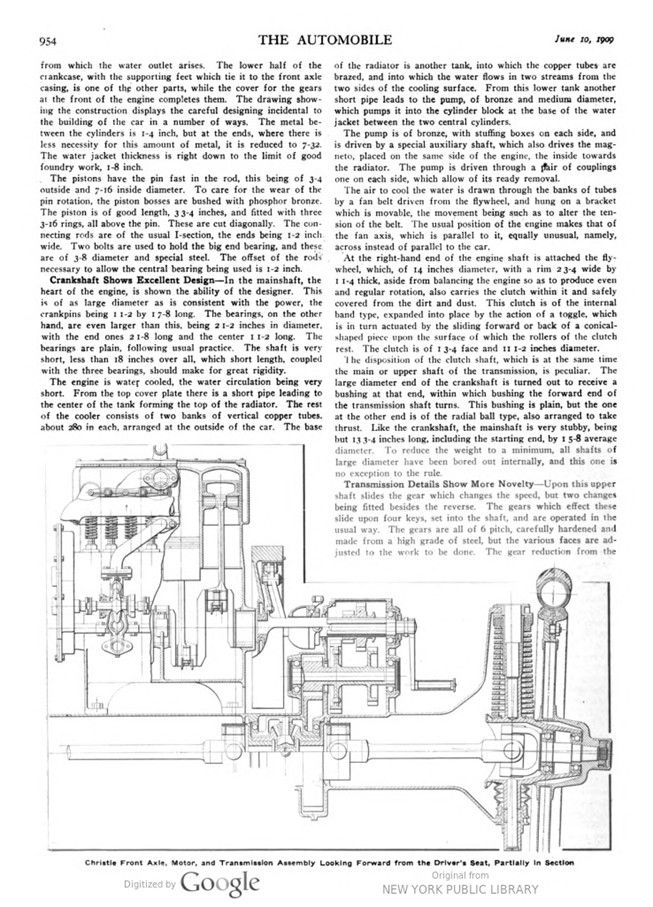
The four cylinders of the engine are cast in a unit with the upper half of the crankcase. The bore is 34 inch and the stroke 5 inch. The engine is slated to deliver at least 18 horsepower, which it does easily at 1,500 r.p.m. The top of the cylinder block, comprising an opening for the core print of perhaps 5 inches wide and 14 inches long, is normally covered by a plate, from which the water outlet arises. The lower half of the crankcase, with the supporting feet which tie it to the front axle casing, is one of the other parts, while the cover for the gears at the front of the engine completes them. The drawing showing the construction displays the careful designing incidental to the building of the car in a number of ways. The metal between the cylinders is 1-4 inch, but at the ends, where there is less necessity for this amount of metal, it is reduced to 7-32. The water jacket thickness is right down to the limit of good foundry work, 1-8 inch.
The pistons have the pin fast in the rod, this being of 3-4 outside and 7-16 inside diameter. To care for the wear of the pin rotation, the piston bosses are bushed with phosphor bronze. The piston is of good length, 33-4 inches, and fitted with three 3-16 rings, all above the pin. These are cut diagonally. The connecting rods are of the usual I-section, the ends being 1-2 inch wide. Two bolts are used to hold the big end bearing, and these are of 3-8 diameter and special steel. The offset of the rods necessary to allow the central bearing being used is 1-2 inch.
Crankshaft Shows Excellent Design – In the main-shaft, the heart of the engine, is shown the ability of the designer. This is of as large diameter as is consistent with the power, the crankpins being 1 1-2 by 17-8 long. The bearings, on the other hand, are even larger than this, being 2 1-2 inches in diameter, with the end ones 21-8 long and the center I 1-2 long. The bearings are plain, following usual practice. The shaft is very short, less than 18 inches overall, which short length, coupled with the three bearings, should make for great rigidity.
The engine is water cooled, the water circulation being very short. From the top cover plate there is a short pipe leading to the center of the tank forming the top of the radiator. The rest of the cooler consists of two banks of vertical copper tubes, about 280 in each, arranged at the outside of the car. The base of the radiator is another tank, into which the copper tubes are brazed, and into which the water flows in two streams from the two sides of the cooling surface. From this lower tank another short pipe leads to the pump, of bronze and medium diameter, which pumps it into the cylinder block at the base of the water jacket between the two central cylinders.
The pump is of bronze, with stuffing boxes on each side, and is driven by a special auxiliary shaft, which also drives the magneto, placed on the same side of the engine, the inside towards the radiator. The pump is driven through a pair of couplings one on each side, which allow of its ready removal.
The air to cool the water is drawn through the banks of tubes by a fan belt driven from the flywheel, and hung on a bracket which is movable, the movement being such as to alter the tension of the belt. The usual position of the engine makes that of the fan axis, which is parallel to it, equally unusual, namely, across instead of parallel to the car.
At the right-hand end of the engine shaft is attached the flywheel, which, of 14 inches diameter, with a rim 23-4 wide by 1 1-4 thick, aside from balancing the engine so as to produce even and regular rotation, also carries the clutch within it and safely covered from the dirt and dust. This clutch is of the internal band type, expanded into place by the action of a toggle, which is in turn actuated by the sliding forward or back of a conical- shaped piece upon the surface of which the rollers of the clutch rest. The clutch is of 1 3-4 face and 11 1-2 inches diameter.
The disposition of the clutch shaft, which is at the same time the main or upper shaft of the transmission, is peculiar. The large diameter end of the crankshaft is turned out to receive a bushing at that end, within which bushing the forward end of the transmission shaft turns. This bushing is plain, but the one at the other end is of the radial ball type, also arranged to take thrust. Like the crankshaft, the main-shaft is very stubby, being but 133-4 inches long, including the starting end, by 1 5-8 average diameter. To reduce the weight to a minimum, all shafts of large diameter have been bored out internally, and this one is no exception to the rule.
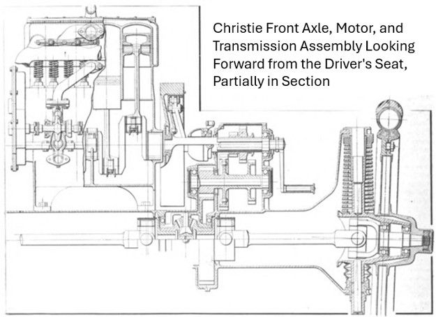
Christie Front Axle, Motor, and Transmission Assembly Looking Forward from the Driver’s Seat, Partially in Section
The Automobile, Vol. XX (20), No. 23, June 10, 1909.
Source: hathitrust.org
Transmission Details Show More Novelty – Upon this upper shaft slides the gear which changes the speed, but two changes being fitted besides the reverse. The gears which effect these slide upon four keys, set into the shaft, and are operated in the usual way. The gears are all of 6 pitch, carefully hardened and made from a high grade of steel, but the various faces are adjusted to the work to be done. The gear reduction from the engine to the road wheels is 4 to 1, and on the low speed just half of that, or 8 to 1. Thus, the gears for the high speed are but 7-8 face, which is increased to 1 inch on the low. This, in turn, is increased to 1 3-4 inches in the gear which carries the final drive to the axles.
This is right below the transmission, and the drive from the latter is by spur gears. The final gear, upon the axle, is attached to the housing of the differential, which is of bronze. The differential, of the bevel type, is located near the center of the axle, the casing of which is split at that point to permit the ready removal of the parts. On each side of this case are large diameter ball bearings, beyond which are the first pair of universal joints, one on each side. From this point to the ends a pair of 11-2 shafts transmit the power to the wheels through the medium of another pair of joints, the latter being located in the exact center of the wheels. This location makes the function of steering easy, for the wheels rotate around the same center about which they move to effect the steering. The axle is housed within a cast bronze tube of 6 3-4 inches outside diameter with 3-16 walls, which is what gives the front view of the car its bulky appearance.
This Form of Drive Calls for Different Springs – Upon the ends of the axle housing are placed the springs, which, from the very nature of the construction, are radically different. They are of the coil variety, the outer diameter of the coil varying from 31-8 at the top to 33-4 at the bottom. The steel comprising the coils is rectangular in section with the longest side in a horizontal plane. The section is 5-8 by 1-4, and each one has 18 full coils. Above the top end and under the lower extremity are placed bronze thrust washers.
What corresponds to the knuckle pin is of very large size, 1 1-2 diameter, bored out inside to 7-8 inch, and projects above the universal joint casing 6 1-2 inches, of which 3 inches has a bearing when the car is not loaded, but with heavy additions to the load this may increase up to 6 inches.
Upon the stub axle end the wheels run on a pair of ball bearings of large size. These are located very close to the line through the wheel center, the inner one being but 1-8 inside of the center of the tire and but 1-16 outside of the center line through the spokes. The axle stub at the inner bearing has the unusual dimension, for this weight of car, of 1 3-4 inches, which decreases to 19-16 at the outer one, but 25-8 farther away.
Beyond this the end tapers, and upon this taper is mounted the heavy hub, which is held in place on the taper by a nut, cottered in position, and further retained in place by the hub cap, which would effectually prevent it from backing off, even if the cotter pin were forgotten.
The rear axle is of very simple construction and is as plain as is consistent with the fact that it carries nothing but the springs and the large-sized brake drums. These brakes are internal expanding and are operated by means of a cam.
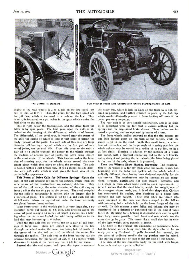
The front wheels incline outward so that the tire centers are one inch farther apart on top than at the bottom, while the gauge is 52 1-2 on the road. With this small tread, a wheel- base of 100 inches, and the large angle of steering possible, the whole vehicle may be turned in a radius of 12 1-2 feet, or in a 25-foot circle. Steering is effected by the medium of a worm and sector, with a diagonal connecting rod to the left knuckle and a straight rod joining the two wheels, the latter being placed in the rear of the axle, where it is protected.
Even the Wheels Show Marked Ingenuity – The construction of the wheels is a far cry from what one would expect, for, beginning with the hubs just spoken of, the whole wheel is radically different, these having been designed especially for the cab service. The requirements may be summed up as: exceptional strength, particularly for side strains; lightness, and of a shape or form which lends itself to quick replacement. It is well known that the steel tube is, weight for weight, one of the strongest shapes made, and it is of this shape that Christie has constructed his spokes, thus obtaining at a bound both strength and light weight. These steel tubes are forced into seats machined in the hubs and then clamped to the felloes with retaining bolts, which hold on the loose flange of the rim as well. In this manner a new felloe and inflated tire may be substituted for a deflated or punctured tire in the time it takes to tell it. By using bolts, brazing is dispensed with and the quick tire change made possible. Both front and rear wheels are the same size, 32 by 3 1-2. This seems like a small size, but in view of the light weight, 2,100 pounds, is ample.
The body is the regular cab equipment of landaulette body, but the bonnet varies, being more like the style affected for so many years by Panhard. It pulls forward for removal, but for cases of ordinary trouble the top portion may be raised. The starting crank may be seen at the left side of this bonnet.
The price of the cab, complete, ready for the road, with lamps, horn, tools and spare parts, is $2,600.
Photo captions.
Page 954 – 955.
Christie Front Axle, Motor, and Transmission Assembly Looking Forward from the Driver’s Seat, Partially in Section
The Control Is Standard – Full View of Front Axle Construction Shows Starting Handle at Left