


Text and jpegs by courtesy of hathitrust.org www.hathitrust.org, compiled by motorracinghistory.com
The Automobile, Vol. XXX (30), No. 16, April 16, 1914
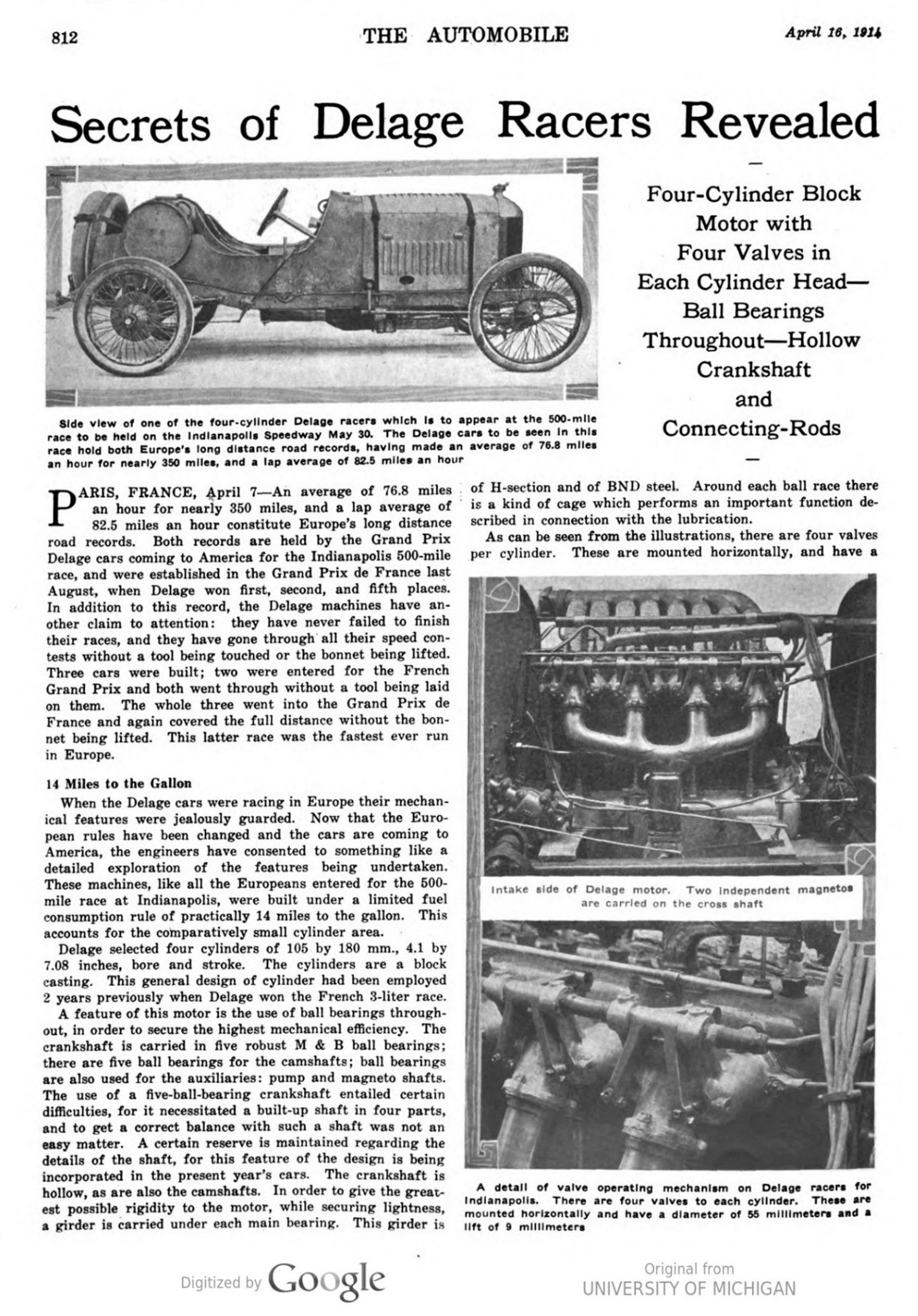
Secrets of Delage Racers Revealed
Four-Cylinder Block Motor with Four Valves in Each Cylinder Head – Ball Bearings Throughout – Hollow Crankshaft and Connecting-Rods
PARIS, FRANCE, April 7 – An average of 76.8 miles an hour for nearly 350 miles, and a lap average of 82.5 miles an hour constitutes Europe’s long distance road records. Both records are held by the Grand Prix Delage cars coming to America for the Indianapolis 500-mile race, and were established in the Grand Prix de France last August, when Delage won first, second, and fifth places. In addition to this record, the Delage machines have another claim to attention: they have never failed to finish their races, and they have gone through all their speed contests without a tool being touched or the bonnet being lifted. Three cars were built; two were entered for the French Grand Prix and both went through without a tool being laid on them. The whole three went into the Grand Prix de France and again covered the full distance without the bonnet being lifted. This latter race was the fastest ever run in Europe.
14 Miles to the Gallon
When the Delage cars were racing in Europe their mechanical features were jealously guarded. Now that the European rules have been changed and the cars are coming to America, the engineers have consented to something like a detailed exploration of the features being undertaken. These machines, like all the Europeans entered for the 500-mile race at Indianapolis, were built under a limited fuel consumption rule of practically 14 miles to the gallon. This accounts for the comparatively small cylinder area.
Delage selected four cylinders of 105 by 180 mm., 4.1 by 7.08 inches, bore and stroke. The cylinders are a block casting. This general design of cylinder had been employed 2 years previously when Delage won the French 3-liter race.
A feature of this motor is the use of ball bearings throughout, in order to secure the highest mechanical efficiency. The crankshaft is carried in five robust M & B ball bearings; there are five ball bearings for the camshafts; ball bearings are also used for the auxiliaries: pump and magneto shafts. The use of a five-ball-bearing crankshaft entailed certain difficulties, for it necessitated a built-up shaft in four parts, and to get a correct balance with such a shaft was not an easy matter. A certain reserve is maintained regarding the details of the shaft, for this feature of the design is being incorporated in the present year’s cars. The crankshaft is hollow, as are also the camshafts. In order to give the greatest possible rigidity to the motor, while securing lightness, a girder is carried under each main bearing. This girder is of H-section and of BND steel. Around each ball race there is a kind of cage which performs an important function described in connection with the lubrication.
As can be seen from the illustrations, there are four valves per cylinder. These are mounted horizontally and have a diameter of 55 millimeters and a life of 9 millimeters. The valve operation is by vertical push rod and a bell crank, Fig. 3, each one having two arms and operating a pair of valves. Lightness has been obtained in these parts, the valve tappets being hollow and only 1 millimeter thick, and the vertical push rods also being hollow and of the same thickness. The exhaust is brought out at an angle of practically 45 degrees, there being a separate pipe from each valve port, Fig. 4, into the long exhaust pipe carried to the rear along the lefthand side of the car. Valve timing is not exaggerated, the exhaust opening having a lead of 45 degrees and the intake closing a lag of 20 degrees. The motor develops 120 horsepower at 1850 revolutions.
BND steel is made use of extensively in the motor. It is employed for the crankshaft, connecting rods, and valve gear. Steel pistons are used with two rings having bayonet type joint. The pistons are drilled; the central portion is of smaller diameter than the top and bottom, and oil grooves are provided. Connecting-rods are hollow and are machined conically. There is a cylinder offset of 25 millimeters, or 1 inch, from crankshaft center.
Two Magnetos Fitted
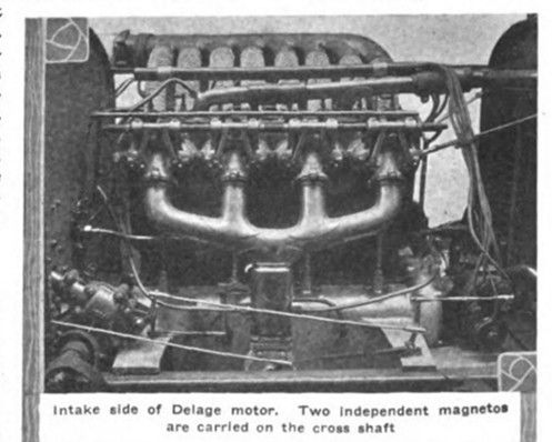
Two independent magnetos are fitted, one driven off the cross shaft operating the water pump, and the other is set fore and aft on the exhaust side.
The eight plugs are mounted in the heads of the cylinders, but as far apart as possible. Each magneto has its own switch, mounted on the dashboard, thus enabling the driver to cut out either magneto for purposes of testing. While the failure of either magneto would not stop the running of the car, it is found that much better results are obtained with the two magnetos firing simultaneously.
Lubrication is interesting. A gear pump in the base chamber and driven off the intake camshaft, delivers oil through a collector to the main bearings. In this collector there is a hand regulated valve and three leads, one to the main bearings, one to the overhead valve gear, and one to the dashboard pressure indicator. With the valve closed the whole of the oil goes to the main bearings and none to the overhead valve gear, the pressure on the indicator thus attaining its maximum. The valve is always kept open a certain amount, allowing a quantity of oil to escape to the valve gear; the pressure indicated on the dash indicator is the actual pressure delivered to the bearings.
Cage Around Each Ball Bearing
As already mentioned, there is a cage around each ball bearing. This insures a constant bath of oil for each bearing, and also enables the bearing to drive out the lubricant centrifugally into collectors delivering it to the connecting rod ends and to the camshafts and piston walls. The system can be described as a centrifugal one, the function of the pump being limited to keeping a supply of oil in the housings around each main bearing. The overflow from the collector is carried up to the axis of the bell cranks. All these are united by flexible tubes, the shafts being hollow, and a complete circuit is maintained in the two sets for respectively exhaust and intake valves. From this lead for the valve gear, there is a return to the base chamber by way of the timing gears.
In addition to the oil in the base chamber, there is a supplementary tank on the dash with a feed to the motor. The flow from this tank is regulated according to conditions under which the motor is running and is made sufficient to maintain the correct level in the base chamber. To prevent an excess, through inattention or any other cause, there is an overflow on the side of the chamber, the superfluous oil being lost on the road. This arrangement makes practically impossible a fouling of the plugs through excess lubrication.
In all their French races these cars have been fitted with Claudel carbureters and Bosch magnetos.

Rigid Mounting for Motor
Rigid mounting is adopted for the motor, which is placed directly on the main frame members. The gearbox, however, has three-point suspension to a couple of transverse frame members. The connection between the two is by multiple- disk clutch. Designed for road racing, the cars have five speeds and reverse, but the first speed is really an emergency gear, and like the reverse is kept covered by a clip on the gate. While the housing is of aluminum, the whole of the interior of the box is of BND steel, the shafts are hollow and are carried on M & B ball bearings.
One of the most interesting features of this set of cars, and one in which the fine workmanship is most apparent, is the rear axle. The material used is BND steel with aluminum for the differential housing. The conical axle tubes are machined out of the solid forging and have a thickness varying from 3 to 4 mm. They are bolted to the central housing, and the halves of this are in turn bolted together around their circumference. The differential housing is a fine piece of work designed with a view to minimum weight and maximum strength. It is deeply ribbed where it receives the bolts attaching it to the axle tubes and has a vertical wall in which is carried the rear bearing of the driveshaft. The driving pinion is thus carried in ball bearings front and rear. The driveshafts are hollow; the differential satellites are bevel type. By reason of the use of high-grade material and correct design it has been possible to get the weight of the complete rear axle to the unusually low figure of 170 pounds. In this weight is comprised the axle complete, the rear universal joint, and the brake drums. This low unsprung weight is responsible, in a very large degree, for the remarkable manner in which the cars hold to the road at high speed.
Broad semi-elliptical springs carried above the axle are relied upon to take the drive, the propeller shaft in consequence having two universal joints.
Car Weighs 1,900 Pounds
Total weight of the car, with tanks empty, is 1,900 pounds. This low weight has been obtained by the use of the highest-grade material in every part. This applies to such parts as brake and change speed levers, change speed gate, brake rods and levers, etc., where dimensions are reduced to what in standard car practice appears like flimsiness, and would indeed be such if special steels had not been employed. Aluminum figures very largely in the makeup of the car. It is used for the bonnet, scuttle dash, seats, floorboards, dashboard. The only wood on the car is to be found in the steering wheel. For participation in the Indianapolis race the cars have undergone few changes. Gear ratio has been modified to suit track conditions; the latest type of Rudge-Whitworth wire wheels has been adopted, and one of the cars at least will carry a streamline tail. In European racing circles the Delages are looked upon as the fastest of the foreign contingent. Certainly, the cars are among the finest examples of racing productions in the Old World, and their appearance against the cream of America assures for Indianapolis a race altogether unequaled in intensity.
Photo captions.
Page 812.
Side view of one of the four-cylinder Delage racers which is to appear at the 500-mile race to be held on the Indianapolis Speedway May 30. The Delage cars to be seen in this race hold both Europe’s long distance road records, having made an average of 76.8 miles an hour for nearly 350 miles, and a lap average of 82.5 miles an hour
Intake side of Delage motor. Two independent magnetos are carried on the cross shaft
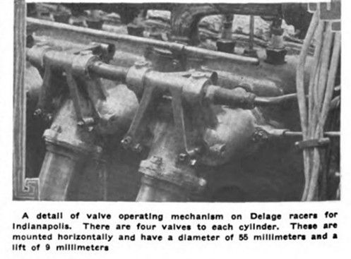
A detail of valve operating mechanism on Delage racers for Indianapolis. There are four valves to each cylinder. These are mounted horizontally and have a diameter of 55 millimeters and a lift of 9 millimeters
Page 813.
Exhaust side of Delage racer for Indianapolis, showing separate pipe for each valve port at 45 degrees angle
Five speed gearbox with three-point suspension used on Delage racer. These cars have five speeds and reverse, but the first speed is really an emergency gear and is covered by a clip like the reverse
Steering wheel and aluminum dashboard used on Delage racers. Note windscreen for driver
Page 814.
Above is shown the aluminum differential housing pinion and universal joint on the Delage driveshaft. Below, rear axle with hollow driveshaft having bearings on both sides