


Text and jpegs by courtesy of hathitrust.org www.hathitrust.org, compiled by motorracinghistory.com
The Automobile, Vol. XXXIV (34), No. 18, May 14, 1916
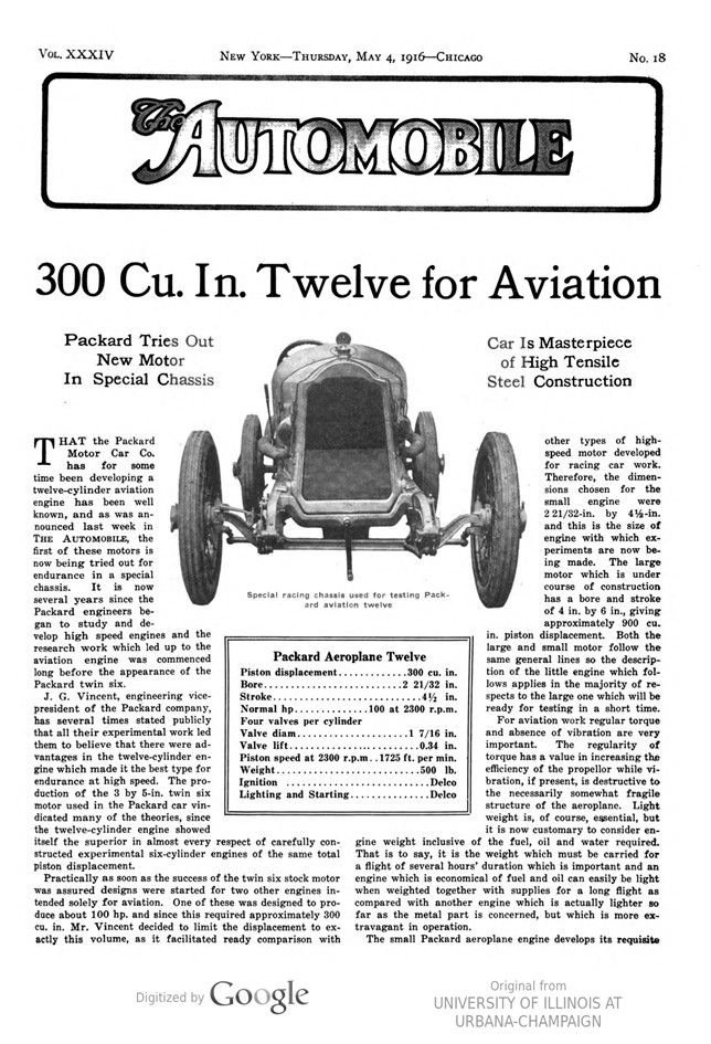
300 Cu. In. Twelve for Aviation
Packard Tries Out New Motor In Special Chassis
Car Is Masterpiece of High Tensile Steel Construction
THAT the Packard Motor Car Co. has for some time been developing a twelve-cylinder aviation engine has been well known, and as was announced last week in THE AUTOMOBILE, the first of these motors is now being tried out for endurance in a special chassis. It is now several years since the Packard engineers began to study and develop high speed engines and the research work which led up to the aviation engine was commenced long before the appearance of the Packard twin six.
J. G. Vincent, engineering vice-president of the Packard company, has several times stated publicly that all their experimental work led them to believe that there were advantages in the twelve-cylinder engine which made it the best type for endurance at high speed. The production of the 3 by 5-in. twin six motor used in the Packard car vindicated many of the theories, since the twelve-cylinder engine showed itself the superior in almost every respect of carefully constructed experimental six-cylinder engines of the same total piston displacement.
Practically as soon as the success of the twin six stock motor was assured designs were started for two other engines intended solely for aviation. One of these was designed to produce about 100 hp. and since this required approximately 300 cu. in. Mr. Vincent decided to limit the displacement to exactly this volume, as it facilitated ready comparison with other types of high-speed motor developed for racing car work. Therefore, the dimensions chosen for the small engine were 2 21/32-in. by 4½-in. and this is the size of engine with which experiments are now being made. The large motor which is under course of construction has a bore and stroke of 4 in. by 6 in., giving approximately 900 cu. in. piston displacement. Both the large and small motor follow the same general lines so the description of the little engine which follows applies in the majority of respects to the large one which will be ready for testing in a short time.
For aviation work regular torque and absence of vibration are very important. The regularity of torque has a value in increasing the efficiency of the propellor while vibration, if present, is destructive to the necessarily somewhat fragile structure of the aeroplane. Light weight is, of course, essential, but it is now customary to consider engine weight inclusive of the fuel, oil and water required. That is to say, it is the weight which must be carried for a flight of several hours‘ duration which is important and an engine which is economical of fuel and oil can easily be light when weighted together with supplies for a long flight as compared with another engine which is actually lighter so far as the metal part is concerned, but which is more extravagant in operation.
The small Packard aeroplane engine develops its requisite 100 hp. at 2300 r.p.m., and its weight is almost exactly 500 lb. The 100 hp., however, is very considerably less than the total ability of the engine, which will run and show increasing power up to speeds in the neighborhood of 4000 r.p.m. At 3300 r.p.m. the first engine gives 130 hp. The power curve is quite smooth as the motor speed falls off and the engine will run quietly and regularly at 300 to 400 revolutions.
It is now several weeks since the first engine was put on the test block and at first it appeared difficult to find spark plugs which would withstand the very high explosion temperature which is obtained in the cylinders. This trouble has been entirely overcome and the test block failed to show any specific weakness in any part.
This being the case, Mr. Vincent I decided to take a leaf out of the book of the Mercedes company and obtain his duration tests by putting the motor in a chassis which would permit it to run at full power for hours on end while exposing it to the shock and other indefinite circumstances that accompany a track test which seem impossible to imitate on the test block. It will be remembered that the Mercedes cars which won the French Grand Prix in 1914 were all fitted with the aeroplane engine which is generally regarded in Europe as being about the best that has yet been constructed. The Packard company has no intention of doing any racing, and it has been necessary to build a special chassis to enable the motor to be tried out properly. For about a week the chassis has been at work at Sheepshead Bay speedway showing lap speeds between 100 and 110 m.p.h. and speeds of 116 m.p.h. on the straightway. This is with a gear ratio giving less than 3000 r.p.m. at 100 m.p.h. No attempt has been made to check the speeds very accurately or to discover the maximum, the bulk of the running being done at about 100 m.p.h., a speed at which the motor is working just a little harder than it would have to work when its speed was held down by the proper size of propeller in an aeroplane.
No one can possibly see the car which is being used to test this motor without regretting very greatly that it will not be seen in competition, since it is one of the prettiest racing machines that has ever been made.
In designing the chassis the endeavor has been to render it very highly efficient while making it strong enough to provide absolute safety, the object being to test the motor, and the greatest possible care has been taken to have the chassis perfect.
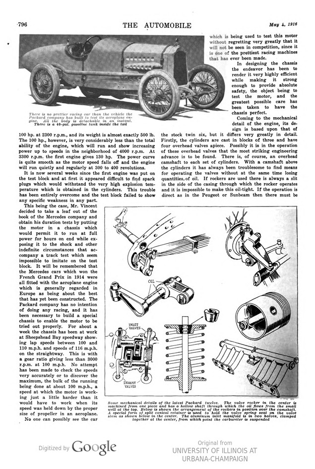
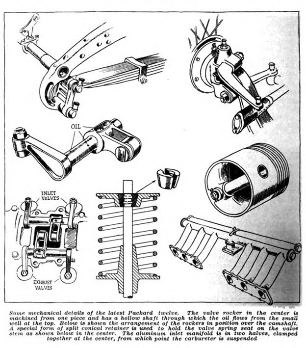
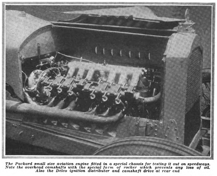
Coming to the mechanical detail of the engine, its design is based upon that of the stock twin six, but it differs very greatly in detail. Firstly, the cylinders are cast in blocks of three and have four overhead valves apiece. Possibly it is in the operation of these overhead valves that the most striking engineering advance is to be found. There is, of course, an overhead camshaft to each set of cylinders. With a camshaft above the cylinders it has always been troublesome to find means for operating the valves without at the same time losing quantities, of oil. If rockers are used there is always a slit in the side of the casing through which the rocker operates and it is impossible to make this oil-tight. If the operation is direct as in the Peugeot or Sunbeam then there must be holes in the bottom of the casing through which the tappets ! pass to reach the valve stems. In the Packard design this trouble has been overcome by cranking the rockers. The lever which rests on the cam and the lever which touches the valve are at opposite ends of a short shaft. This means that the bearing of the rocker comes between the cam end, which is in an oil box, and the valve end which is outside. The length of the bearing provides a perfect oil seal so that the cam mechanism can be lubricated copiously and yet the valves will remain perfectly clean. This layout can be readily understood by referring to the photograph of the motor.
Considerable thought was given to the best methods for driving the camshaft, and, by making comparative layouts, it was found that the balance of the advantages favored the use of trains of spur gears. One of the most important advantages is that the parts of the spur gear trains are very simple and there are no thrust bearings required. Spur gears can be cut from very hard material and finished very highly so that there is no error in the timing due to backlash. Actually in this Packard motor when erected it was found that the maximum error in valve timing was 1 deg. on the flywheel which, as any engineer knows, is a remarkable achievement.
For a variety of reasons the rear location is chosen for the spur gears, the crankshaft pinion coming just in front of the flywheel bearing. Owing to the high grade of material the gears are quite narrow, that on the flywheel being only 5/8 in. wide.
For the connecting-rods the stock arrangement has been abandoned and the forked type used instead of the side by side. The reason for this is that the former arrangement is lighter. With an L-head twelve-cylinder engine, if the valves are well proportioned, the length becomes such that there is plenty of room for side-by-side rods. With the overhead valve, four-valve type of cylinder the length is so greatly reduced that there is not even room for forked rods, if the valves are taken as the limiting factor. Thus, having commenced with the valves the engine was lengthened just enough to give proper bearing surface for forked rods. These rods are made from very high tensile steel of I-beam section and are machined all over; an oil tube carries the lubricant to the piston pin.
Has Unique Crankshaft
The crankshaft is very unusual as the webs are triangular in end elevation. This design was developed by experiments made to discover the design which would provide the greatest rigidity with the least weight. For both the main bearings, of which there are three, and the crank pins, the diameter is 1 7/8 in., but the triangular webs are so strong that the shaft is completely free from whip throughout the whole speed range. It has already been stated that the connecting-rods are very light and this lightness extends to the pistons. These are die-cast aluminum alloy and the whole piston assembly with four rings and piston pin complete weighs 11 oz.
It is when the valves are examined analytically that one of the advantages of the twelve-cylinder construction appears. In these little cylinders, 2 21/32 bore, there is room for four valves 17/16 in. in the clear. The angle of seat is 45 deg. and the lift 0.34 in. This gives 1 sq. in. of valve opening for each 17 cu. in. of piston displacement. The 300-cu. in. Mercedes four-cylinder aeroplane engine has the largest valves which can be accommodated, and the valve opening in that engine is 1 sq. in. for each 25-cu. in. displacement.
Another advantage appears when the piston speed is studied since a 42-in. stroke at the normal running speed of 2300 r.p.m. gives a piston speed of only 1725 ft. per min. A detail which shows up well in the illustration and yet may appear peculiar, is the design of the intake manifold. This is the result of much experiment and is giving better service than designs which appear to be a theoretical improvement. Mr. Vincent explains the success of its design as follows:
In an intake the resistance to gas flow comes at the corners or bends and the resistance of the bend is much greater than the resistance in straight pipe. It is thus important that if there be any bends they should all be in the same position relative to the valves served. In this particular manifold the gas rising from the carbureter impinges against the top of the fore and aft pipe, where it spreads, and the distance from each valve to the main header is the same. As a method of demonstrating the accuracy of carburetion and the evenness of charge obtained with this manifold, the fact may be mentioned that when the engine is run without the exhaust manifold the length of the jet of flame from each cylinder is the same. You could hold a straight edge to the tips of the flames and none would overlap it any more than another.
Electric Starting for Air Work
All Packard aviation engines will be supplied with starting and lighting equipment. For this purpose Delco has developed a special small generator design for the high average speed of aeroplane service. This is mounted accessibly between the cylinder blocks. Having the generator and a small battery there seemed no need for any other ignition device than the Delco distributer, which has given such complete satisfaction on the stock twin six. Consequently, one of these is mounted at the rear end of the V. As soon as these engines are ready for delivery, which will be in quite a short time, they will be offered either with the starting and lighting equipment with Delco ignition or without any other electrical equipment but two magnetos. Up to the present the distributer has shown itself well up to the demands made by continued high-speed running.
For cooling, there is a single pump with a double outlet and this is mounted at the front of the crankcase, having its spindle vertical and a bevel gear drive from the front end of the crankshaft; there is no thermostat control. The lubrication system is on the same lines as the stock Packard motor, that is to say, each main bearing of the crankshaft is fed with high pressure oil, which is then taken to the crank pins and passes up to the piston pins. The various auxiliaries are fed independently and the two camshafts are fed from inside.
Has High Compression, Timing Normal
Two other facts about this engine which have a bearing on the power are the compression and the timing. The compression volume is designed to be 17 per cent of the total volume, giving a gage compression of about 110 lb. This high compression pressure is rendered possible by the small size of cylinder and the high thermal conductivity of the pistons, but it has a very destructive action on the spark plugs. The plug, with which all the tests have been made and which appears to be entirely satisfactory, is the Rajah, this being an ordinary stock pattern and not a special model. Mr. Vincent stated that one of these plugs could be heated red hot with a blow torch and then dropped into cold water without any damage to the porcelain.
The timing is quite ordinary:
Inlet opens 5 deg. after top center. – Inlet closes 40 deg. after lower center.
Exhaust opens 47 deg. before lower center. – Exhaust closes 5 deg. after top center.
It will be noticed that the exhaust closes and the inlet opens at the same instant, but there is no overlap.
It is well understood that one of the advantages of four-valve construction is that the smaller valves need but light springs. This is particularly true with the very small parts in the Packard engine since the valves are so light that the spring pressure required is quite small. Actually, the pressure of the spring when the valve is fully open is only 52 lb., this falling to 38 lb. when the valve is closed.
Rear Axle Cost $1,000
A few words may be added about the chassis in which this engine is being tested for it is no less remarkable a piece of work in its way. The gearset bolts to the crankcase and the steel flywheel contains a single disk clutch of very light construction. Back of the gearset there is a large and very powerful transmission brake, this being metal-to-metal, as are the rear wheel brakes, all the shoes being cut out from high tensile material so as to obtain great rigidity with minimum weight. The rear axle has a chrome nickel steel housing in two parts split vertically in the center and each half is turned from a solid billet of steel. It is stated that each of these halves cost over $350, bringing the price of the axle to $1,000 or over. The steering gear has been specially designed also and, like the rest of the chassis, is made of the strongest steel that can be obtained.
There is no need to say anything about the shape of the body as this is sufficiently described by the illustrations. Its method of attachment, however, is not so obvious. At the tip of the tail a small socket will be noticeable. This contains a bolt which holds the top part of the body in place. At the front end by the cowl there is a pair of hinge clips. The pins for these form the attachment for the two ends of the rear hood strap. Thus, to remove the body the hood strap is taken off, the two hinge pins unhitched and removed, and the single bolt at the tip of the tail taken out; the body can then be lifted off complete. To give it ample lateral security a steel sill is carried along the top of the frame, the body setting into this, and there are a number of dowel pins along each side. The chassis altogether represents a distinct advance upon the best work which Europe has so far produced.
Photo captions.
Page 795.
Special racing chassis used for testing Packard aviation twelve
Page 796.
There is no prettier racing car than the vehicle the Packard company has built to test its aeroplane engine. All the body is detachable in an instant. There is a 40-gal. gasoline tank inside the tail
Some mechanical details of the latest Packard twelve. The valve rocker in the center is machined from one piece and has a hollow shaft through which the oil flows from the small well at the top. Below is shown the arrangement of the rockers in position over the camshaft. A special form of split conical retainer is used to hold the valve spring seat on the valve stem as shown below in the center. The aluminum inlet manifold is in two halves, clamped together at the center, from which point the carbureter is suspended
Page 797.
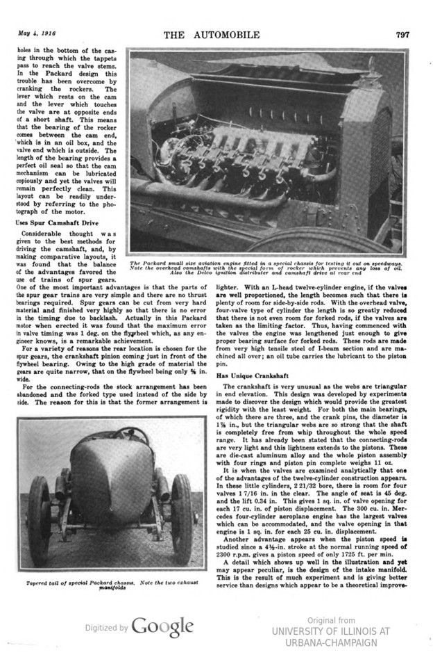
The Packard small size aviation engine fitted in a special chassis for testing it out on speedways. Note the overhead camshafts with the special form of rocker which prevents any loss of oil. Also the Delco ignition distributer and camshaft drive at rear end
Tapered tail of special Packard chassis. Note the two exhaust manifolds
Page 798.
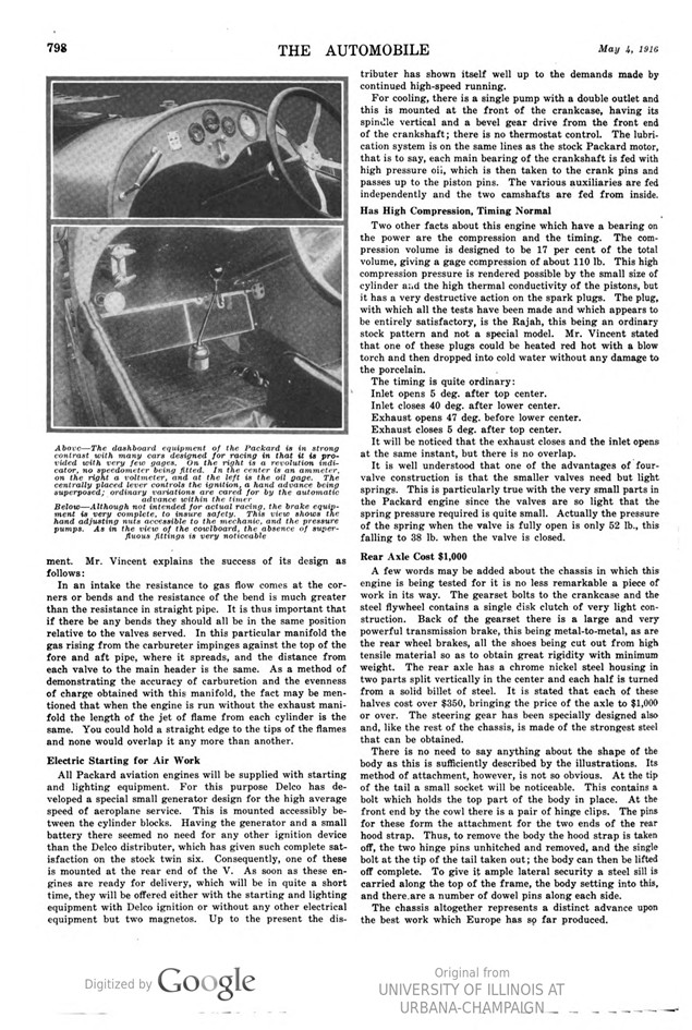
Above – The dashboard equipment of the Packard is in strong contrast with many cars designed for racing in that it is provided with very few gages. On the right is a revolution indicator, no speedometer being fitted. In the center is an ammeter, on the right a voltmeter, and at the left is the oil gage. The centrally placed lever controls the ignition, a hand advance being superposed; ordinary variations are cared for by the automatic advance within the timer
Below – Although not intended for actual racing, the brake equipment is very complete, to insure safety. This view shows the hand adjusting nuts accessible to the mechanic, and the pressure pumps. As in the view of the cowlboard, the absence of superfluous fittings is very noticeable