Text and jpegs by courtesy of hathitrust.org www.hathitrust.org, compiled by motorracinghistory.com
The Automobile, Vol. X (10), June 18, 1904
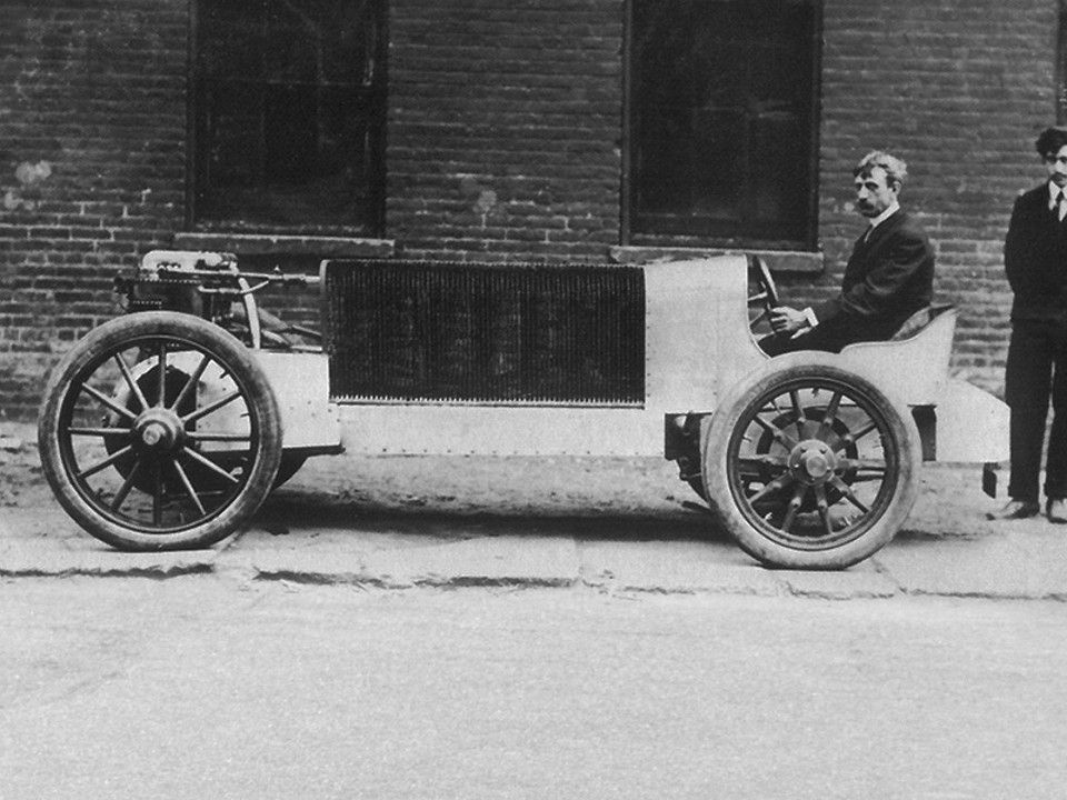
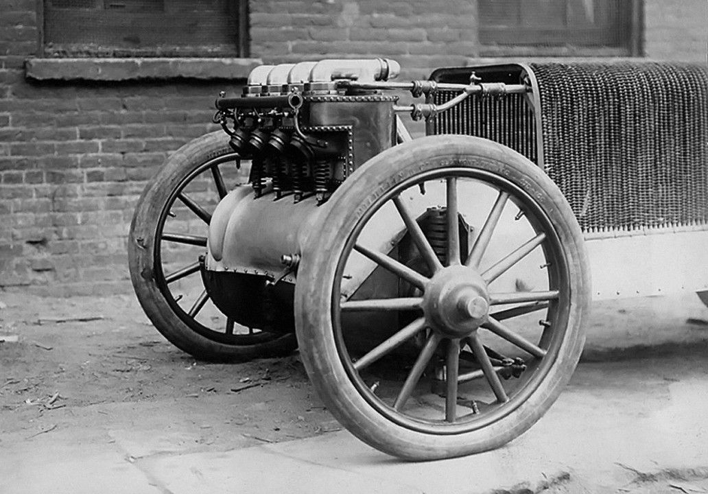
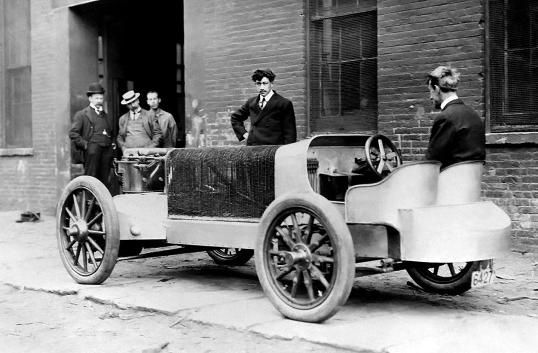
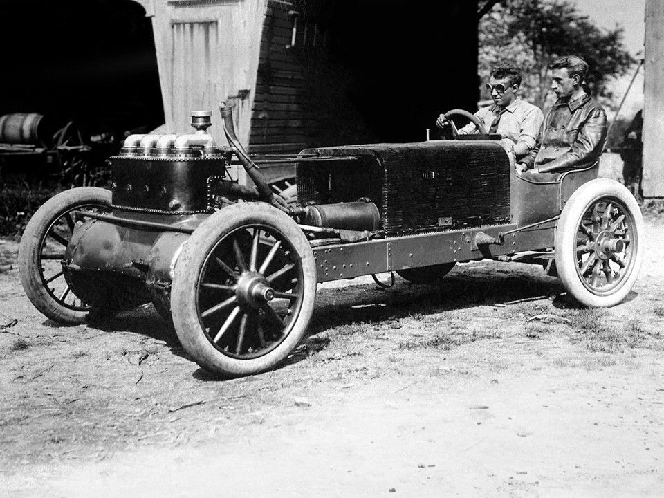
Walter Christie’s Front Wheel Drive of 1904.
In 1904 the US patent #761,657 was granted to Walter Christie on a front-wheel drive system.
This patent is described in The Automobile of June 18, 1904 as follows:
Front Drive Car.
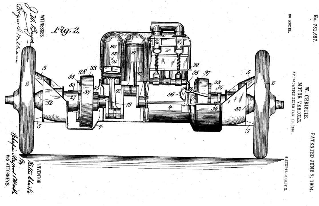
No. 761,657. – W. Christie, of New York. This is the Christie car which has been so prominent of late in various American track events. The motor is placed transversely in front, and in the high speed drives the front wheels by direct connection at each end. There is no front axle, its place being taken by a casing, of which the motor crank case forms a part, which extends clear across from one steering knuckle pivot to the other. The side members of the frame are bolted to this casing, but it is not a dead weight on the wheels, for the ends of the casing rest on helical springs between the casing and the knuckles, taking the place of the usual front side springs. As there is necessarily relative movement between the knuckles and the motor shaft, on account of both the steering and of the play of the springs, short cardan shafts are included in the connections between them. The low gear (there is but one) is produced by a back gear and countershaft, and the reverse by a second countershaft and intermediate pinion. There is no compensating gear in the direct drive, it being impossible to put one there; but this is not considered a drawback, as the car is built mainly for straightaway racing and the motor may readily be unclutched for the turns. A compensating gear is however included in the low gear countershaft.
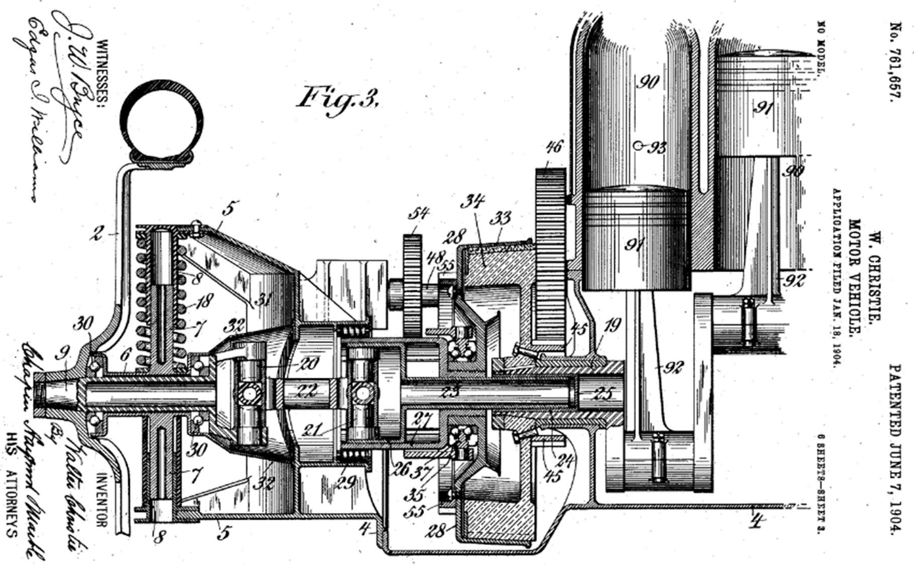
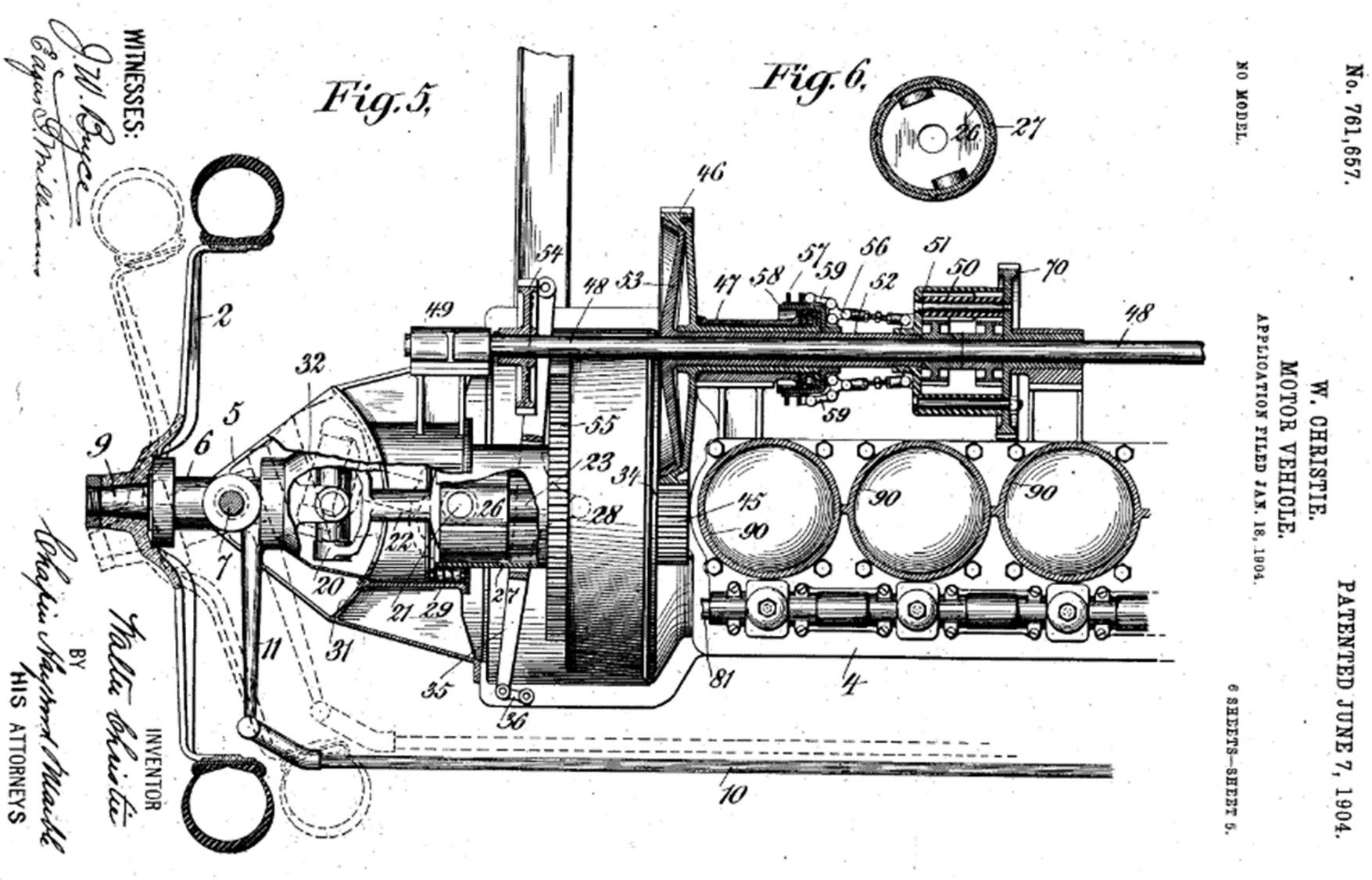
The drawings show respectively a vertical section through the center of the motor, casing, etc., and a plan view of the same parts with the differential and countershaft gears in section. A front wheel is indicated by 2, which is dished as shown to bring the steering pivot in the plane of the rim. It is secured to the short shaft 9, which runs in the swiveling sleeve 6, on which are formed the pivot pins 7 of the steering knuckles. On the inner end of 9 is formed a portion of one of the universal joints at the ends of the short cardan shaft 22.
The transverse front casing as a whole is indicated by 4. It is closed in where it forms the crank case, open over the gears, and closed around the cardan shafts, of which there is one driving each front wheel. At the ends of the case are formed top and bottom horns 5, to which the sleeves 8 guiding the pivots 7 are fixed. One of the front springs is represented by 18, on which the weight of the casing, motor and front mechanism generally rest. The horns are connected by a curved portion 31 of the case, in which a dust cover 32, attached to 6, moves in such a way as to exclude dust whatever the movement of 6.
Each end 19 of the crank shaft carries a flywheel 34, which drives the adjacent cardan shaft through a conical clutch as follows: The shaft is bored and bushed, and in it runs loosely a hollow shaft 23, having an enlarged cup-shaped end 26 containing one of the universal joints 21. The end 26 is splined in a deep cup 27, whose outer end runs in roller bearings 29 in the case, and whose inner end is fast to the moving member 28 of the clutch. Thus 27 and 28 may be shifted axially by the shifting fork 35 and ball thrust ring, to engage or disengage the clutch, and 26 may move axially in 27 to accommodate the play of the springs and the deflection of the steering knuckles, without affecting the positive rotatory connection of 26 and 27. See dotted lines in plan view. In the machine as shown, the clutch is held in engagement, not by a spring, but by a positively locked hand lever imposing a constant thrust on 28. This lever engages the clutches on both flywheels at the same time by an equalizing device.
On one of the two flywheels is a pinion 45, in constant mesh with gear 46, carried loosely on the divided countershaft 48 in the bearing seen. Inside of the gear hub is the sleeve hub of a cone clutch member 53, prolonged to a rigid connection with the shell of the differential 50. This clutch is tightened by a thrust collar acting on toggles 56, which are operated by a separate hand lever. The drive from the countershaft is through gears 54, which are normally out of mesh, but which are engaged by gear wheels 55, attached to clutch member 28, when the latter are shifted more than just enough to release the clutches. Reversal is effected by another shaft, not shown, on which is a gear meshing with 46, and a loose pinion, locked to the shaft by a friction clutch, and driving gear 70 on the differential through an intermediate pinion to reverse the direction. The clutch is engaged by a foot pedal.
Brakes are applied to the rear wheels, which otherwise are trailers only. The patent has 101 claims.