


Text and jpegs by courtesy of hathitrust.org www.hathitrust.org, compiled by motorracinghistory.com
The Automobile, Vol. XXVI (26), No.20, May 16, 1912
Wire Wheel Again Comes to the Front
Lightness, Flexibility, Strength Against Vibration and Shock, and Tire Economy Points in Its Favor
Mode of Manufacture as Carried on at the McCue Company’s Plant
HISTORY repeats itself. Wire wheels, used exclusively in automobiles when this type of vehicle first made its appearance, had to make room for wood wheels when the industry developed further. But if the wire wheel maker’s art had not progressed far enough when the automobile entered the roads of the world, this art quietly developed during the last decade, and today stands ready to challenge the wood wheel industry, although the latter’s products are found on an overwhelming majority of cars now in operation, especially in this country. Laboratory and road tests, as well as races of all kinds, demonstrate the virtues of wire wheels in a forcible way, so that manufacturers cannot help sitting up and taking notice of the wheel that has come back.
Wire wheels, when compared with wood wheels, show these principal points of difference. They are lighter and more flexible. Other advantages claimed for them are greater strength, both against vibration and shock, and increased tire economy. The reasons for the latter feature are that owing to the elastic wire spokes, the rim starts and stops gradually, whereas if mounted on a wooden wheel it experiences more or less of a jerk in either case. Then there is the fact that wire wheels keep very cool even if rotating rapidly and are thereby enabled to radiate the heat generated by the tires, while wood retains a great amount of heat; so that in the latter case the tires are not cooled and rubber and fabric are bound to suffer from the effects of this condition.
A material difference between wire and wood wheels lies also in the utilization of the tensile strength of wire wheels as compared with the compressive strength of wood wheels. In long beams, such as the spokes represent, the tensile strength is very much in excess of the compressive strength. Furthermore, the wire wheel divides the work of transmitting torque and of resisting lateral strains into the functions of two sets of spokes, and, moreover, uses the set designed for the latter work to protect the driving spokes from shock. A final advantage claimed for wire wheels is that they are not very apt to skid.
A wire wheel properly made represents a flexible system, in which the hub is suspended in a position of stress balance. As wire wheels are made today they are easily removed and replaced on their hubs, offering all the advantages of demountable rims with a lesser weight. The heaviest type of McCue touring car wheel fully assembled weighs 16 pounds.
The wire wheel made by the McCue Company, Buffalo, N. Y., is of the double-row spoke type, there being two rows of wire spokes holding the hub suspended centrally in the axis of the rim. The relative position of the two rows of spokes is shown at II in Fig. 1, while I represents a spoke of the inner row and Jone of the outer row. Owing to the shape of the hub, the inner spokes are shorter than the outer ones, but they exceed them in number, there being forty-two inner spokes and twenty-eight outer ones. The spokes are joined in pairs, or, rather, two spokes are formed of one piece of wire passing through two openings in the cast-steel hub casing and being attached at two different points of the rim. The two spokes formed by one wire thus cross at an angle, and this angle is greatest in the inner row.
How Wire Wheels Are Assembled
In the manufacture of the wheels, tension is applied to both ends of each wire and they are held under this tension by means of the nipples which hold them to the rim. The same tension is applied to all spokes so that they hold the hub in a central position, the stresses in action being tensile in the spokes, the bursting stress in the hub and the compression to which the rim is subjected. In operation the functions of the outer and inner spokes are widely different. The inner spokes I, Fig. 1, presenting short and nearly perpendicular connections between the rim and hub axis, take up the driving strains, and it is for this reason that their number exceeds that of the outer spokes.
The suspended hub is able to equalize itself to strains set up in the wheel, and the amounts of torque carried by inside and outside spokes respectively are proportional to the products of numbers and tangential radius of each set of spokes. There being forty-two inner spokes and twenty-eight outer ones, with tangential radii proportioned as about 4 to 1 (P to S), the ratio of torque carried by the two sets of spokes is as follows:
Inner spokes / Outer spokes = (42 X 4) / (28 X 1) = 6 / 1.
Furthermore, the load-carrying capacity of the spokes depends on the cosines of angles A for the inner and B for the outer set, and since these angles are very small the cosines are very near 1. There is also a relation between the load-carrying capacity and the angle formed by a pair of spokes made of one wire, and for this reason the tangential radius of the inner spokes must not be too great.
Distribution of the Strains
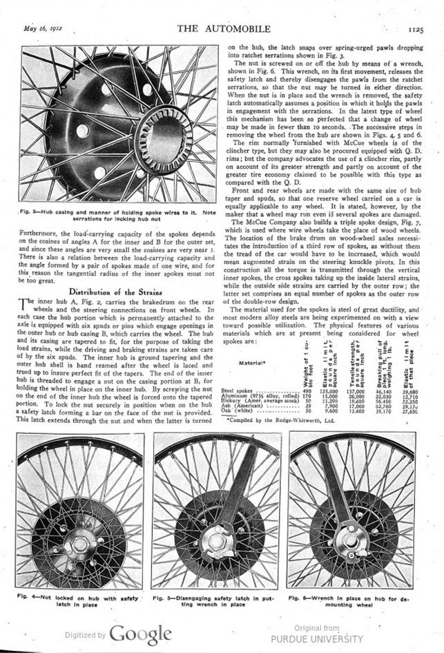
The inner hub A, Fig. 2, carries the brake drum the rear wheels and the steering connections on front wheels. In each case the hub portion which is permanently attached to the axle is equipped with six spuds or pins which engage openings in the outer hub or hub casing B, which carries the wheel. The hub and its casing are tapered to fit, for the purpose of taking the load strains, while the driving and braking strains are taken care of by the six spuds. The inner hub is ground tapering and the outer hub shell is hand reamed after the wheel is laced and trued up to insure perfect fit of the tapers. The end of the inner hub is threaded to engage a nut on the casing portion at B, for holding the wheel in place on the inner hub. By screwing the nut on the end of the inner hub the wheel is forced onto the tapered portion. To lock the nut securely in position when on the hub a safety latch forming a bar on the face of the nut is provided. This latch extends through the nut and when the latter is turned on the hub, the latch snaps over spring-urged pawls dropping into ratchet serrations shown in Fig. 3.
The nut is screwed on or off the hub by means of a wrench, shown in Fig. 6. This wrench, on its first movement, releases the safety latch and thereby disengages the pawls from the ratchet serrations, so that the nut may be turned in either direction. When the nut is in place and the wrench is removed, the safety latch automatically assumes a position in which it holds the pawls in engagement with the serrations. In the latest type of wheel this mechanism has been so perfected that a change of wheel may be made in fewer than 10 seconds. The successive steps in removing the wheel from the hub are shown in Figs. 4, 5 and 6. The rim normally furnished with McCue wheels is of the clincher type, but they may also be procured equipped with Q. D. rims; but the company advocates the use of a clincher rim, partly on account of its greater strength and partly on account of the greater tire economy claimed to be possible with this type as compared with the Q. D.
Front and rear wheels are made with the same size of hub taper and spuds, so that one reserve wheel carried on a car is equally applicable to any wheel. It is stated, however, by the maker that a wheel may run even if several spokes are damaged.
The McCue Company also builds a triple-spoke design, Fig. 7, which is used where wire wheels take the place of wood wheels. The location of the brake drum on wood-wheel axles necessitates the introduction of a third row of spokes, as without them the tread of the car would have to be increased, which would mean augmented strain on the steering knuckle pivots. In this construction all the torque is transmitted through the vertical inner spokes, the cross spokes taking up the inside lateral strains, while the outside side strains are carried by the outer row; the latter set comprises an equal number of spokes as the outer row of the double-row design.
The material used for the spokes is steel of great ductility, and most modern alloy steels are being experimented on with a view toward possible utilization. The physical features of various materials which are at present being considered for wheel spokes are:
Material* – Weight of 1 cubic foot – Elastic Imit, pounds per square Inch – Tensile strength, pounds per square Inch – Breaking pull of piece 1 ft. long, weighing 1 lb. – Elastic limit of that piece
Steel spokes 490 135,000 157,000 46,140 39,68
Aluminum 170 15,000 26,000 22,030 12,710
(97% alloy, rolled)
Hickory 50 11,200 19,600 56,450 32,250
(Amer. average stock)
Ash (American) 39 7,900 17,000 62,760 29,170
Oak (white) 50 9,600 13,600 39,170 27,650
*Compiled by the Rudge-Whitworth, Ltd.
Photo captions.
Fig. 1 – McCue wire wheel. A – inner hub with brake drum, B – outer hub with wheel
Fig. 2 – Scheme of spoke arrangement. A-outer-row spoke, B-relation of two spoke sets, C-inner row spoke, D-triple-row spoke design
Fig. 3 – Hub casing and manner of holding spoke wires to it. Note serrations for locking hub nut
Fig. 4 – Nut locked on hub with safety latch in place
Fig. 5 – Disengaging safety latch in putting wrench in place
Fig. 6 – Wrench in place on hub for demounting wheel