

Text and jpegs by courtesy of hathitrust.org www.hathitrust.org, compiled by motorracinghistory.com
Motor Age, Vol. XLII (42), No. 18, November 2, 1922
Review of Racing Car Construction
Intimate Views and Descriptions of Three Popular Speed Engines
THAT motor car racing contests are beneficial to the industry from anything but a publicity standpoint is doubted by many and supported by a few. Without entering into a useless discussion let us pick out a few facts that will bear investigation and analysis.
The greatest difficulty experienced by the owner and the builder of the very early cars was the tendency of the mechanism to lay down and quit at times, without any provocation.
Then followed on era when practically any engine could be depended on to start and run practically continuously until its functioning was ended by the breakage of some vital part.
The breakage of vital parts of the engine and chassis was not an uncommon occurrence among American cars previous to 1908. If the advertising copy of the, then, medium and popular priced car is referred to, the investigator will find that in the majority of factory ads particular emphasis was laid on the „Oversize axle designed for a 60-hp. engine,“ the „Oversize transmission,“ and the „Sturdily constructed 30-hp. engine.” The trend in short was to make the part heavier if it had developed defects, rather than proportion the part according to the duty imposed on it. Thus the breakage of the various parts was solved to some extent by increasing their size.
The famous Pope Toledo, which was considered one of the best American cars in performance, was hopelessly out- classed in competition encountered in Europe in the time of the early Grand Prix races. The German Mercedes and Benz, the Italian Isotta and Fiat, and French Panhard and Darracq, and the British Napier and Rolls had, at that time, been developed to a much greater state of perfection through the lessons learned in racing. The laboratory equipment of today was not then in existence. The results of owners‘ experiences had not supplied the necessary development data so that the punishment any mechanism could assimilate was determined by its behavior in a race. It is true that the performance of any chassis in the hands of thousands of different owners will give an excellent idea or just what part or unit is in need of re- vision, but it is a slow method, and at that time the thousands of owners were not available.
If we review the history of the automotive industry in this country it will be found that practically every manufacturer whose activities date back to the years previous to 1909 has, at some time, engaged in racing, for instance some of the well-known cars of today, Buick, Chalmers, Studebaker (then known as the E. M. F.), National, Marmon, Mercer, Apperson, Locomobile, Oldsmobile, Case and Packard.
Invasion by the Foreigners
The 300-in., high speed, light weight Peugeot was brought to the U. S. in 1913 and in competition at Indianapolis that year won handily the 500-mile race. It was brought over here after a very successful two years of racing in France. The construction and design incorporated several features that were as yet untried in the United States because American designers had not then developed any high speed 300-in. engines. The crankshaft speed of the Peugeot was slightly over 3000 r.p.m. The scavenging type of hollow crankshaft lubrication was then practically unknown here, and the overhead camshaft without the use of rockers an innovation. Four valves per cylinder, an aluminum cylinder block, and an aluminum alloy differential housing were other features that less revolutionary to American designing practice of that day. A similar car campaigned during 1915 and 1916 by Resta won the majority of speed contests for that period.
Has Racing Affected the Trend?
It may have been merely coincidental, but nevertheless, since 1913 the trend has been toward higher crankshaft speeds, light weight construction or, more aptly, „proportioned“ construction of the entire chassis and hollow crank- shaft lubrication. The horsepower to weight ratio has been materially reduced and better performance and greater tire mileage has been secured with equal perhaps greater liability. The tendency has been towards engines of less displacement and today. the engine of 450-in. displacement is rarely seen. The 300-in. stock car engine of today is doing the work of the 450-in. engine of 1911.
The power produced by any internal combustion engine is directly proportionate to the amount of fuel it can burn in given time. Or rather the amount of heat it can extract from a given amount of fuel in a given time. Figured on a basis of cu. in. displacement per minute, the 183-in. small-bore high-speed engine has considerably more than half the displacement of the 450-in. medium speed engine. As an illustration, the 183-in., Duesenberg, straight eight, racing engine delivers 114 hp. at 4,250 r.p.m., or its displacement in cubic inches per minute is 183 X 4,250 or 777,750 cubic inches per minute. The 450-in. engine delivered its maximum at about 2,400 r.p.m., its displacement is then 450 + 2,400 or only 1,080,000 in. per minute.
In 1911 there existed one school of design the product of which was the slow to medium speed engine with a weight to power ratio of approximately 13 to 1. Since 1911, even among the so- called conservatives, this ratio has been reduced to about 912 pounds to the horsepower. Though not carried as high as the average 300-in. racing engine, the crankshaft revolutions of the Marmon, Cadillac, Pierce-Arrow, Winton, Packard and Peerless, taken on an average, are at least 25 per cent higher than in their 1911 engines. The popular and medium price class shows a comparatively higher average crankshaft speed at maximum power. These are some of the things that must be considered before it can be truthfully and definitely stated that racing has been of no benefit to designing. Finally it should be remembered that racing furnishes a forum for information that can be put into practice, without the necessity of every manufacturer taking an active part in racing competition.
Three American designers have been most active in representing America at the annual 500-mile race at Indianapolis and on other tracks during the season. Whether their efforts and experience gained during this time will profit them remains to be seen, nevertheless at least one of these men has modified his racing chassis slightly and is now offering it as a stock car on the open market. The Packard Co. has recently announced its intention to engage actively in racing this season, for engineering reasons. Mercedes, Sunbeam, Fiat and A. C. have done extensive development work on the 122-in. engine and, no doubt, one or more cars bearing these name plates will be pitted, next year, against the best America can offer.

Duesenberg Straight Eight
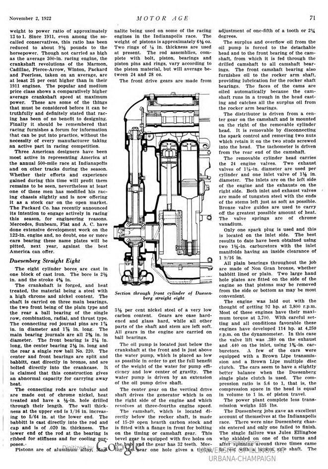
The eight-cylinder bores are cast in one block of cast iron. The bore is 2162 in. and the stroke 45% in.
The crankshaft is forged, and heat treated, the material being a steel with a high chrome and nickel content. The shaft is carried on three main bearings, the two front being of the plain type and the rear a ball bearing of the single row, combination, radial, and thrust type. The connecting rod journal pins are 1-7/8 in. in diameter and 1-7/8 in. long. The main bearing journals are all 2-3/8 in. in diameter. The front bearing is 2-1/8 in. long, the center bearing 2½ in. long and the rear a single row ball No. 220. The center and front bearings are split and babbitt, cast directly in bronze, and are bolted directly into the crankcase. It is claimed that this construction gives an abnormal capacity for carrying away heat.
The connecting rods are tubular and are made out of chrome nickel, heat treated and have a 12-in. hole drilled through their length. The wall thickness at the upper end is 1/16 in. increasing to 5/64 in, at the lower end. The babbitt is cast directly into the rod and cap and is of .020 in. thickness. The lower end of the rod at the bearing is ribbed for stiffness and for cooling purposes.
Pistons are of aluminum alloy, Magnalite being used on some of the racing engines in the Indianapolis race. The weight of pistons is approximately 642 oz. Two rings of 1/8 in. thickness are used at present. The rod assemblies, complete with bolt, piston, bearings and piston pins and rings, vary according to the piston material, but will average between 24 and 28 oz.
The front drive gears are made from 3½ per cent nickel steel of a very low carbon content. Gears are case hardened and glass hard, while all other parts of the shaft and stem are left soft. All gears in the engine are carried on ball bearings.
The oil pump is located just below the crankshaft at the front and is just above the water pump, which is placed as low as possible in order to get the full benefit of the weight of the water for pump efficiency and low center of gravity. The water pump is driven by an extension of the oil pump drive shaft.
The center gear on the vertical drive shaft drives the generator which is on the right side of the engine and which revolves at three-fourths engine speed.
The camshaft, which is located directly below the rocker shaft, is made of 15-20 open hearth carbon stock and is fitted with a flange in front for bolting on the timing or camshaft gear. This bevel gear is equipped with five holes on the hub, and the gear has 32 teeth. Moving the gear one hole gives a timing adjustment of one-fifth of a tooth or 214 degrees.
The surplus and overflow oil from the oil pump is forced to the detachable head and to the front bearing of the camshaft, from which it is fed through the drilled camshaft to all camshaft bearings. The front camshaft bearing also furnishes oil to the rocker arm shaft, providing lubrication for the rocker shaft bearings. The faces of the cams oiled automatically because the cam- shaft runs in a trough in the head casting and catches all the surplus oil from the rocker arm bearings.
The distributor is driven from a center gear on the camshaft and is mounted on the right of the removable cylinder head. It is removable by disconnecting the spark control and removing two nuts which retain it on the two studs screwed into the head. The tachometer is driven from the rear end of the camshaft.
The removable cylinder head carries the 24 engine valves. Two exhaust valves of 1 1/8-in. diameter are used per cylinder and one inlet valve of 1½ in. diameter. The inlets are on the left side of the engine and the exhausts on the right side. Both inlet and exhaust valves are made of tungsten steel with the ends of the stems left just as soft as possible. Bronze valve guides are used to carry off the greatest possible amount of heat. The valve springs are of chrome vanadium.
Only one spark plug is used and this is located on the inlet side. The best results to date have been obtained using two 112-in. carburetors with the inlet manifolds having an inside clearance of 1 9/16 in.
All plain bearings throughout the job are made of Non-Gran bronze, whether babbitt lined or plain. Two large hand hole plates are fitted on the side of the engine so that pistons may be removed from the side or bottom as may be most convenient.
The engine was laid out with the thought of getting 92 hp. at 3,800 r.p.m. Most of these engines have their maximum torque at 3,700. With careful setting and all conditions favorable these engines have developed 114 hp. at 4,250 r.p.m. on the dynamometer. In this case the valve lift was .380 on the exhaust and .440 on the inlet, using 1¾-in. carburetors. A few of the cars were equipped with a Brown Lipe transmission and a Brown Lipe multiple disc clutch. The cars seem to have a slightly better balance when the Duesenberg single plate clutch is used. The com- pression ratio is 5.6 to 1, that is, the compression space in the head is equal in volume to 1 in. of piston travel. The power plant complete less transmission weighs 535 lbs.
The Duesenberg jobs gave an excellent account of themselves at the Indianapolis race. There were nine Duesenberg chassis entered and only one failed to finish. The single failure was Jules Ellingboe who skidded on one of the turns and after spinning around three times came to rest with a broken axle shaft. The eight remaining Duesenbergs all finished in the money and in the following order: Hartz, second; DePalma, fourth; Haibe, fifth; Wonderlich, sixth; Fetterman, seventh; Vail, eighth; Thomas, tenth.
The chassis construction of each of the Duesenbergs was similar, except that Wonderlich’s car used the four-wheel brake system during the race. The eight other chassis were equipped with these brakes but the other drivers did not consider them necessary and they were disconnected.
The rear axle housings on these cars were built to the specifications of the Duesenberg Co. by the Columbia Axle Co. The front axle is a special Duesenberg design of tubular construction to accommodate the Duesenberg system of hydraulic braking. The tubular member acts as the fluid supply line to the brake actuating pistons on each axle spindle. The rear axle shafts are made of molybdenum steel. A 15-52 rear axle ratio was used on practically every one of the cars. This ratio allowed the engine to turn up a maximum of approximately 4,000 r.p.m. on the Indianapolis track. The wheelbase of the cars is 106 in. and 32×4-in. tires were used in front while the rear tires, in most cases were 32×42 in. The layout is extremely accessible, and it claimed that the engine can be completely dismantled in two hours.
The cars raced at Indianapolis were only slightly different in detail from the stock car now marketed by this company. The engine changes consisted only in higher compression, the use of eight-volt ignition, lighter pistons and the mounting of all gears on ball, instead of plain, bearings.
Miller Engined Chassis
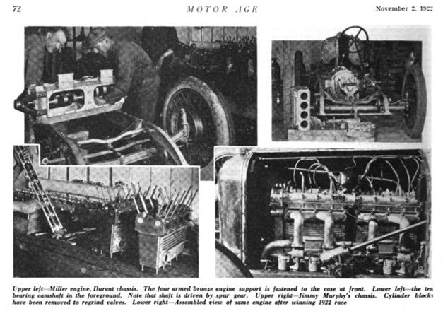
Harry Miller of Los Angeles is the designer and builder of the engines in the Murphy Special, the Leach Special of Elliots, the Leach Special of Miltons, and the Durant Special driven by Cliff Durant.
The eight cylinders are cast in two blocks of four. Bore 2 11/16 in., stroke 4 in. Lightness and a clean appearance has been secured by machining the cylinder blocks all over on the outside. The cylinders are of the solid head type with the exception of the one in Elliot’s car, which has a detachable cylinder head. Detachable aluminum side plates act as the water jackets for the cylinders. These plates are retained by countersunk head screws and are ribbed for purposes of heat radiation. The inlet and exhaust passages are of rectangular section with rounded corners, one inlet and one exhaust port for each cylinder being brought outside for attachment of the manifolds. The effort of the designer to get a clean layout is depicted in the method of retaining the cylinder blocks to the crankcase. The holding-down studs of the blocks register with corresponding holes in the top face of the crankcase and the nuts are put on from below, and inside the crankcase.
The crankcase is designed for three point support, the rigid anchorage being at the rear. The front support is a spigoted fitting of bronze having four arms. The fitting is detachable from the crankcase and because of its high conductivity is an aid in conducting the heat from the case to the chassis frame.
The three-bearing crankshaft is very similar to the Duesenberg crankshaft and is of massive proportions especially at the crankpin webs. The front bearings are 2% in. in diameter of the plain, bronze backed, babbitt faced type. The rear bearing relieves the plain bearings of all end thrust and is of the single row annular ball type. The shaft is drilled throughout its length for dry sump scavenging lubrication. The curved crank cheeks of large proportions are visible in the view of the crankcase assembly shown above. Considerable trouble was experienced with the eight-cylinder shaft initially as it was found that continued running at high speed developed well defined cracks on the sur- face of the steel. Actual breakage of the shaft did not occur, but it was apparent that something akin to fatigue of the metal was taking place. This trouble was overcome by the use of a heat treated shaft of heavier section at the crank pin cheeks.
The design of the connecting rods is similar to the Duesenberg, both being of the tubular type with a very thin wall section. The lower ends are ribbed on rod and cap for heat radiation and strength. The pistons are of aluminum alloy of Miller design and manufacture and carry rings 1/8 in. wide.
The valve system on this engine is worthy of mention and is interesting from a constructional standpoint. Two camshafts, receiving their drive through a train of ball bearing mounted gears, are used for actuating the 32 valves of the engine. The valve action proper is of the modified Hispano Suiza type, eliminating the use of rocker arms. The actuating mechanism of each shaft is mounted in two aluminum housings. The lower housing, which is retained with the upper housing by means of long cylinder studs, serves as a guide for the eight thin-walled cups which transfer the movement of the cams to the valve stems. These thin-walled cups are fitted with a small nib or dowel which is an integral part of the cup to prevent their rotation in the lower housing, and are acted on directly by the camshaft.
Each camshaft and housing assembly is split vertically, midway between the cylinder blocks, as shown in cut. The halves of the camshaft are joined by flanges and bolts at the point where the housings are split. It is claimed that this two-piece construction prevents any distortion due to movement or lack of alignment between the two blocks. Easier machining and accessibility are also gained by this construction.
The spur gear on the end of each camshaft is fastened to the camshaft flange by four bolts which permit or very close timing adjustment. Ten plain bearings in each upper housing assembly support the camshaft and permit of a shaft of comparatively small diameter.
The sixteen thin cups in each housing, previously referred to, bear directly on the stems of the sixteen inlet and exhaust valves, on each side of the engine. The diameter of inlet and exhaust valves is 1 3/16 in. The angle mounting of these valves allows for ample water jacketing of the valves and spark plugs. The spark plugs, one to a cylinder, are mounted almost directly over the top and center of the combustion chamber. A hole is bored through the inner and outer jackets and a thin walled steel bushing is screwed into the opening thus made. The spark plug is screwed into this opening and is entirely surrounded by water.
Lubrication is secured by forcing oil through the drilled crankshaft from whence it is conducted up to the camshaft housing, lubricating the valve-actuating mechanism. Surplus and overflow oil returns to the pump located at the bottom of the engine. The return path of the surplus oil is over the train of camshaft driving gears.
The ignition generator is located just in front of the front gear housing and is driven from a gear on the crankshaft. The Delco ignition distributor is driven from the left-hand camshaft, the spark advance movement being secured by use of a Bowden wire control.
The intake passages are cored to take a 12-in. carburetor of Miller design and manufacture. On account of each cylinder having its own individual inlet port, the use of multiple carburetors is an easy installation. The engines used by Durant, Elliot and Murphy were fitted with four inlet manifolds feeding two cylinders each and using four single carburetors. Milton’s engine utilized eight separate inlet manifolds connected to four Miller duplex type carburetors having one float mechanism for two separate mixing chambers. The carburetor throttle valves are interconnected and synchronization of the throttle valve opening is secured through adjustment of clamps on the serrated throttle shafts.
The engine develops well over 4,000 r.p.m. before showing a drop in power. The Miller engine in the Murphy SpeIcial won the 1922 International Sweepstakes race at Indianapolis and established a world’s record for the distance.
The Miller engine in the Leach Special driven by Milton gave no trouble during the race but was forced to quit because of a broken gas tank mounting. Although the Miller engined Leach Special driven by Elliot and the Durant Special did not finish in the money, they were running at the finish of the race.
The Frontenacs
The four-cylinder models of the Frontenac, which have been previously described in these columns, are notable because of the great amount of aluminum used in their construction.
The eight-cylinder engine incorporates a block casting of cast iron. The bore is 25% in. and the stroke 4 7/32 in. The valve actuating mechanism is similar to the four-cylinder models which incorporate a light finger interposed between cam and valve stem. There are four valves per cylinder and two camshafts are used. The crankcase is of aluminum and carries five plain bearings which journal the five-bearing crankshaft. Four-point mounting, using tubes that pass through the crankcase, is the method of suspending the engine in frame.
Photo captions.
Page 70.
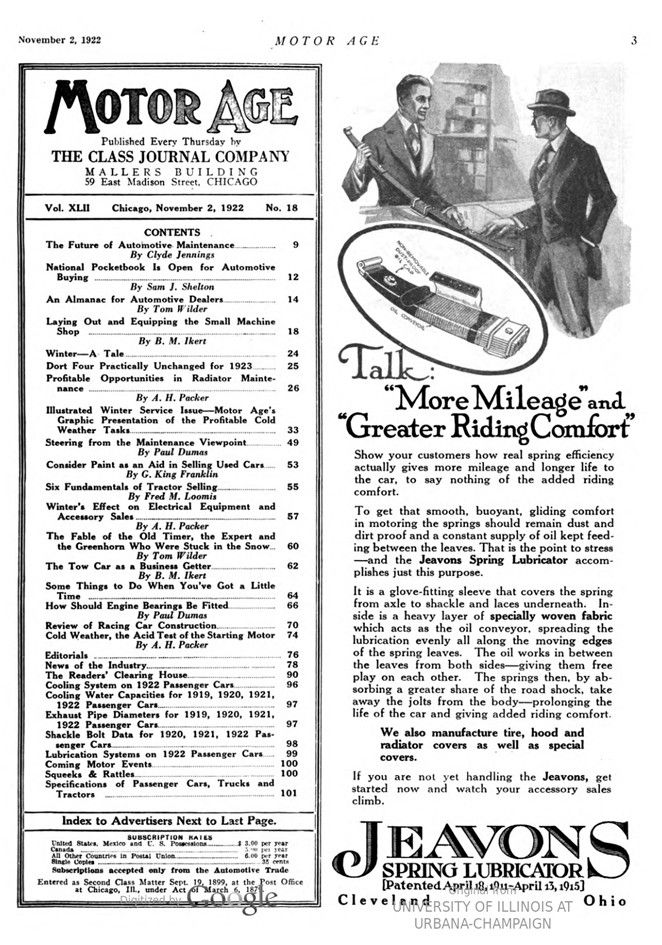
Center – Assembled view of Duesenberg engine. Note that rocker shaft is mounted directly above camshaft. An aluminum cover not shown encloses the valve action mechanism. Two Miller carburetors are used. Left-Same chassis with cylinder head removed. One of the drop forged brake drums with machined cooling nibs is visible at the extreme right.
Right – The camshaft bearings which are located in the cylinder head did not have perfect contact and they are being touched up with the scraper
Page 71.
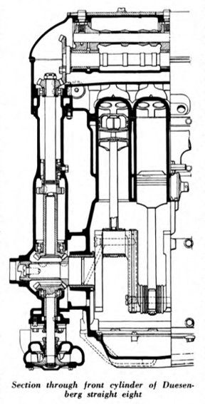
Section through front cylinder of Duesenberg straight eight
Page 73.
Section through four-cylinder Frontenac engine. Large breathers are designed to assist in cooling crankcase interior
Left – Open valve model Frontenac four in Leon Duray’s chassis. Center – Latest model enclosed valve four-cylinder engine as used by Mulford at Indianapolis. Note double drop on chassis frame to give lower center of gravity. Right – Frontenac eight in Baker’s car. This engine has five main bearings as contrasted with three in the Miller and Duesenberg jobs.
Page 72.
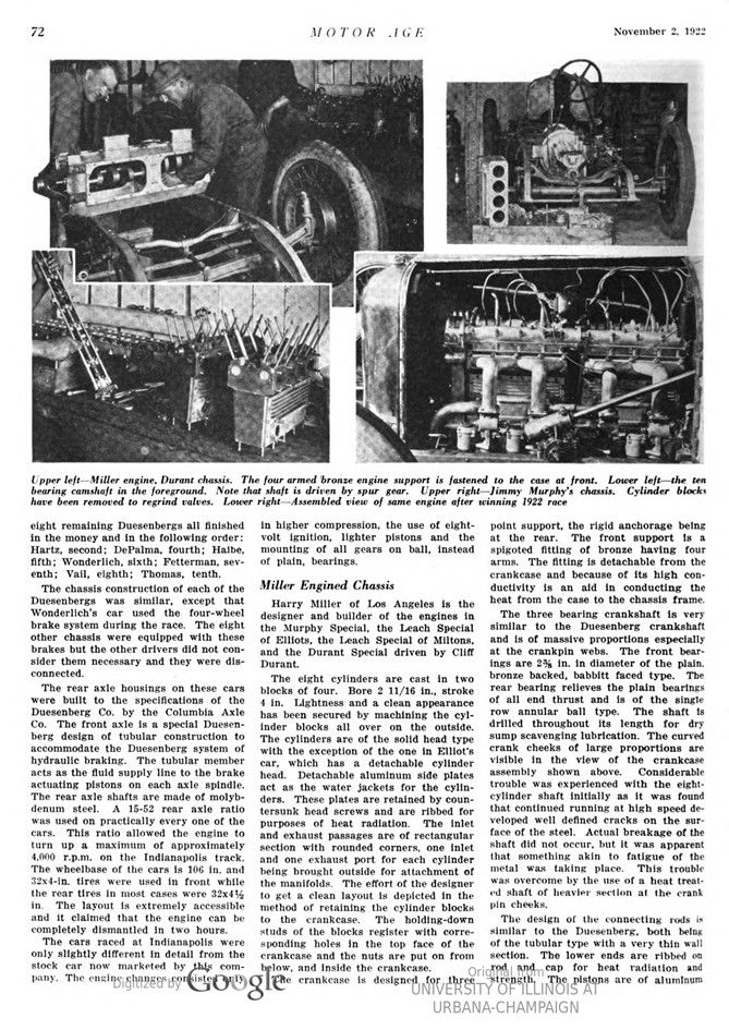
Upper left – Miller engine, Durant chassis. The four-armed bronze engine support is fastened to the case at front.
Lower left – the ten-bearing camshaft in the foreground. Note that shaft is driven by spur gear.
Upper right – Jimmy Murphy’s chassis. Cylinder blocks have been removed to regrind valves.
Lower right – Assembled view of same engine after winning 1922 race