


Text and jpegs by courtesy of hathitrust.org www.hathitrust.org, compiled by motorracinghistory.com
The Automobile, Vol. XXI (21), No. 11, September 9, 1909
MERITORIOUS FEATURES OF WIRE WHEELS
By Joseph A Mackle
IN the early days of the history of the automobile, solid-tired wire wheels were standard practice, and for the low powers and low speeds of those times the wheels gave satisfactory service. Less success was experienced when speeds increased, for owing both to too light construction and to undue imitation of the bicycle form of wheel-which, as shown below, is quite unsuited for automobile work-wire wheels gave considerable trouble and were soon replaced by artillery wooden wheels of the present day type.
One British car, however, had wire wheels of suitable design and shape even at that early date. This was the Lanchester, whose designers have seen so many of their distinctive ideas first ridiculed and afterwards generally adopted. Such matters as three-point suspension forced lubrication and worm drive of rear axle are all general developments of Lanchester practice, and, in passing, the opinion may be hazarded that further Lanchester features of tiller steering, wick carbureter, epicyclic gearing and uncanted front wheels are likely to find a good following in the near future. This reference to Lanchester practice is evoked by the fact that it was the excellence of the results given by those wire wheels that led the directors of the Rudge-Whitworth firm to study the advantages of this form. After lengthy experiment on the part of this great bicycle concern, the first Rudge-Whitworth wire wheels were fitted to the 90-horsepower Napier – the earliest six-cylinder racing car – which appeared in the British eliminating trial for the 1905 Gordon-Bennett race. The wheels showed their value by standing up when MacDonald skidded at high speed against the curbstone at Ramsey corner; but a still better proof was afforded later by Earp’s 100-mile record ride at Ormond Beach, when he covered the last 63 miles on the rim, while in spite of this, the average speed was nearly 90 miles per hour.
Such incidents showed the value of the wire wheel, and undoubtedly its popularity was assured, even if progress were slow. Meanwhile, however, the detachable rim had been extensively introduced for Continental races, and this suggested a detachable form of wire wheel. When the Rudge-Whitworth detachable wheel was at length placed on the market it immediately jumped into favor. Almost every make of car has been fitted with the wheels for special orders, while for this season the leading British firms – Daimler and Napier – fit Rudge-Whitworth wheels as standard on all their cars.
Edict Forbidding Their Use Proves Their Worth – Possibly the widest possible publicity obtainable was given to the wire wheels by the refusal of the Commission Sportive to allow the Napier cars to use these fittings in last year’s Grand Prix race at Dieppe. Under these circumstances, S. F. Edge withdrew his cars, and his action was endorsed by the failure of several of the French cars through defective detachable rims. The embargo on the detachable wheel was withdrawn after the race, but as there has been no big European contest since then, the wheels have not had an opportunity to demonstrate their superior value in this very severe service.
The advantages of the wire wheel lie in its strength and lightness, while equally obvious are the special benefits accruing from the detachable form. A change of wheel can be made inside the space of ten seconds – this, of course, exclusive of the time occupied in jacking up the wheel axle. This ease of changing is not only of service in case of a puncture or blow-out, for by carrying a couple of, or even one, spare wheel with studded tire, the car becomes equally prepared for wet roads or dry.
A set of 888 x 120 mm. wire wheels weighs about 50 pounds less than the corresponding wooden artillery wheels, and the lessened weight of rim seems to have a saving effect on the tires. Particularly is this noticeable on rough roads through the absence of pounding. The greater ease of cooling through the rim serves in a notable degree to prevent the tires from becoming unduly heated at high speeds. Extremes of temperature and climate exercise an extremely deleterious effect on wooden wheels, however well the timber has been seasoned, and for this reason in particular wire wheels are now specified on all British cars required for export to the colonies. Wood is beginning to be reckoned an unreliable and unsuitable material for standing the abnormal stresses to which every automobile part is subjected, and following on its early abolition from the frame, wood has given place to steel, aluminum, and pressed steel for body work, and it is now being succeeded in most cases by steel wire for the material of spokes used in the road wheels. In view of the fact that the strongest claim made for the wire wheel is its ability to withstand a side blow, such as would be occasioned by a sideslip against a curbstone, it is interesting to refer to certain tests made at the Rudge-Whitworth works under the observation of disinterested experts.
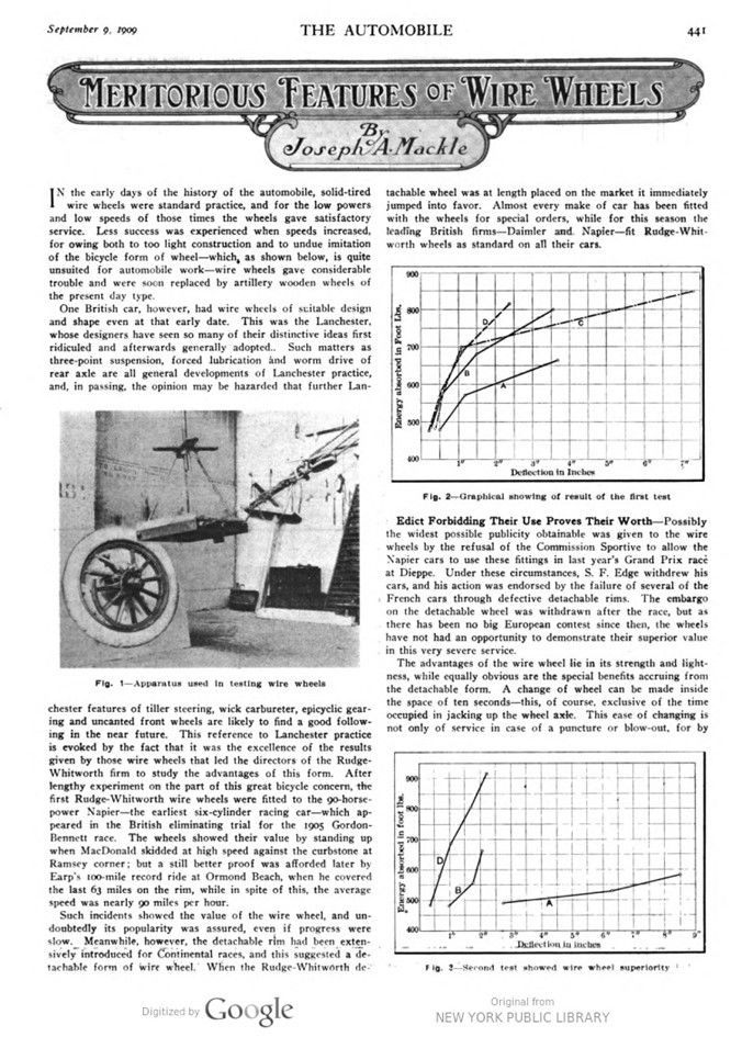
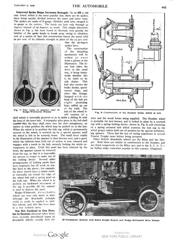
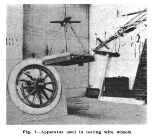
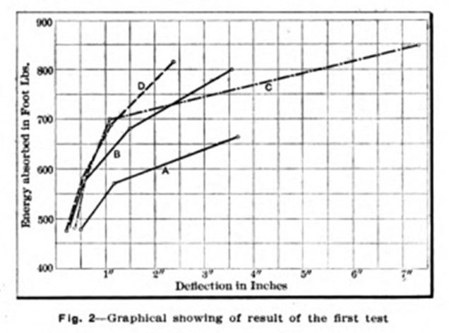
Disinterested Tests Prove Claims Beyond a Doubt – A heavy weight was suspended by a rod from the roof in the manner of a pendulum, in such a way that with the rod in a vertical position the weight rested against the rim of the wheel to be tested, while the wheel itself was supported on a dummy hub. The pendulum was then drawn up to a predetermined height and suddenly released, so that a heavy blow was given to the rim of the wheel. Successive blows increased in magnitude, and the results are shown graphically in Fig. 2. The wooden wheels indicated at A and C were greatly distorted after the first two blows, and at the fourth blow, wheel C collapsed altogether. The wire wheels B and D show only a slight advantage over the wooden wheels for the first blow, but subsequent heavy impacts have comparatively small effect, and even with the maximum deflection that was produced, the rims retained their circular shape to a considerable extent, so that they would still be capable of supporting the weight of the car. A further test of the three wheels was made by striking the rims at a point diametrically opposite to that of the first experiment. The wooden wheel, A, quickly collapsed, but both wire wheels gave substantially the same figures as in the previous test.
Experiments of this kind have led makers to guarantee that a wheel of 888 x 120 mm. size (practically 4¾ x 35 inch), weighing 2014 pounds, with rim, spokes and nipples, will sustain without damage a side pull of 6,000 pounds applied at the rim. The best artillery wheel yet tested, weighing 31½ pounds, would not sustain more than 4,500 pounds. This amounts to an advantage in strength (guaranteed) of 33 per cent. in favor of the wire wheels which are over 35.7 per cent. lighter in weight.
Regarding the construction of the Rudge-Whitworth wheels, the two rows of spokes are not yet symmetrical, as in the case of a bicycle. The stresses set up in a car wheel, particularly when rounding a corner, are very much greater from the outer than from the inner side of the wheel. For this reason, the wheels are considerably dished, so that the outer spokes follow a much sharper cone than the inner. This displacement of the center line amounts to 7/8 inch in a wheel size 888 x 120 mm. Furthermore, in the case of driving wheels, the outer spokes are made tangential to a much smaller circle than the inner spokes, so that the latter take the major portion of the driving stresses, leaving the outer spokes free to resist the side stresses.
Improved Spoke Shape Increases Strength – In an 888 x 120 mm. wheel, which is the most popular size, there are 60 spokes, these being equally divided between the inner and outer rows. The spokes are n made of 8-gauge (British) steel wire, swaged to 10 gauge at the centres. The heads are bent only through 45 degrees instead of 90 degrees, as usual. This simple alteration, shown in Fig. 5, has been found to decrease very greatly the liability of the spoke heads to break away owing to vibration, and, as a matter of fact, this construction leaves the metal with 90 per cent. of its ultimate strength in place of the 75 per cent. that the 90-degree spokes have.
The construction of the detaching mechanism will be evident at once from a glance at the illustration. The inner hub takes the drive in the usual way, it being immaterial whether this is by shaft or by side chains. This hub also carries the brake drums, speedometer rings, and other like fittings. Integral with the body of the hub are eight projecting keys, milled up out of the solid. The hub of the wheel itself consists of a shell which is internally grooved so as to make a sliding fit with the keys of the inner hub. A triangular pilot piece in the hub shell insures that the keys shall enter into the slots straightway, no matter in what position the wheel may be pushed on to the hub. When the wheel is in position the hub cap, which is permanently secured to the wheel, is screwed up by a special spanner until the wheel is felt to be securely home. The small lever visible in the illustration of the spanner is then thrown over, and a pawl, which has hitherto been held out of action, is now released and engages with a notch in the hub, securely locking the whole arrangement in place. Until this pawl has been released by the lever, the spanner cannot be removed from the cap, so that it is impossible for anyone to forget to make use of the locking device. Several other arrangements of locking pawls have been employed, but all work on similar lines to the above; for example, the latest wheels have a simple ratch- et internally cut round the edge of the wheel hub and a spring pawl on the lock nut. When the wheel is in position no backward movement of the cap is possible till the spanner is used to depress the pawl.
Rudge-Whitworth detachable wheels are now only made in wire, although the detachable principle could as easily be applied to artillery wheels, and, this has been done in a few isolated cases.
Use Not Confined to One Firm, but Is General – Several other firms have recently introduced types of detachable wheels, usually both the wire and the wood forms being supplied. The Humber wheel is probably the best known and is locked in place by a screwed cap with a spring locking device, shown in Fig. 8, and consisting of a spring actuated bolt which connects the hub cap to the wheel proper unless held out of position by the special withdrawing spanner. These had the test of racing experience in several Tourist Trophy races before being accepted.
Other British detachable wheels are the Riley and the Harper. Both these are similar in construction to the Humber and are fitted respectively to the Riley cars and to the S. C. A. T. – an Italian make somewhat popular in this country (England).
Photo captions.
Page 441.
Fig. 1 Apparatus used in testing wire wheels
(Energy absorbed in Foot Lbs. 900 800 D/ C 700 600 B 500 400 2″ 37 4″ Deflection in Inches 5″ 6″ 7″)
Fig. 2-Graphical showing of result of the first test
(Energy absorbed in foot lbs. 900 800 700 600 500 B A 400 1″ 2″ 8″ 4″ 5″ Deflection in inches 6″ 8″ 9″)
Fig. 3-Second test showed wire wheel superiority
Page 442.
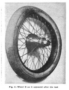
Fig. 4-Wheel B as it appeared after the test
Fig. 5-New and stronger shape given to the spokes. Patent New Bend. – Old Bend.
Fig. 6-Inner and outer hubs of detachable wheel showing driving keys
Page 443.
Fig. 7-Two views of spanner used on Rudge-Whitworth Wheels
1316 Fig. 8-Construction of the Humber wheel, which is new
Front Hub Centre Line of Wheel Back Hub Centre of Wheel 16 Wood Wheel
22- Horsepower Daimler with Silent Knight Engine and Rudge-Whitworth Wire Wheels
(In the same issue of „The Automobile“, September 9, 1909, this was reported some pages later)
WIRE WHEELS SHOW PROGRESS
Modern automobilists, who are deeply interested in the subject of weight, and its immediate effect upon such items as tire mileage, repairs and per-mile-cost, will doubtless peruse the timely article elsewhere in this issue. on the subject of wire wheels with more than ordinary attention. Many experienced motorists favor light-weight construction, but when this is applied to the subject of wheels, they sidestep, with vague and non-committal remarks about side strength.
The old superstition relative to this subject was that the wire wheel had much strength other than that necessary to sustain sidewise application of force. This has persisted and persisted until it might be said with truth that it has been the only formidable barrier to the popular adoption of this type of wheel. In fact, so deeply is this grounded that it is to be found in many books, one widely circulated work commenting as follows:
„Now while it is widely conceded that a wire wheel will sustain a greater load than a wood wheel, the two being considered weight for weight, it certainly will not sustain as great a strain sideways, which represents the line of the wheel’s greatest weakness. A wire wheel driven against a curb with sufficient force will have its rim dented, with the result of loosening all of its spokes and ruining it. A wooden wheel, on the other hand, may have a gap in it and still be serviceable. It may even run with several spokes broken off,“ etc.
As dispelling in an effective manner this twenty-year-old superstition, attention is again called to the article mentioned above. In this there is a brief but convincing description of tests made on such wheels in England, in the course of which tests, wood wheels of the usual artillery pattern were tested under parallel conditions. The results show plainly why these wheels are so extensively used in England, since the old idea of lack of side strength is not only dispelled but unbiased tests prove that the opposite of this is actually the case, the wire wheel possessing a superior strength to its artillery competitor. Second to nothing else in showing this is the accompanying series of tests, in which, having already put one of the artillery wheels out of business, the wire wheels surpassed the remaining wooden competitor by a tremendous margin. This test was in the nature of a reverse stress. Now, it is well known in engineering that the most severe stresses, and those which are most destructive, are alternations of stresses: applications of force from two opposite directions. Yet, it was under that very kind that the wire wheels stood up best. So, it may fairly be said that a slight revision of our ideas relative to wheels is very much in order.
Viewed from a purely utilitarian standpoint, it means that the devotees of long touring can carry a complete spare wheel with tire, at the same total weight for the five wheels and tires, in case wire wheels are used, as the ordinary motorist with but four wheels and tires (those on the four wheels) of the wooden artillery type. That is to say, the weight of one whole wheel and tire is saved by the use of wire-spoked wheels.
Note: Elsewhere in this chapter separately, a graphical evaluation and comparison will be given on the results of the different pendulum test that have been performed by the different institutions during this timeframe. GrocerJack.