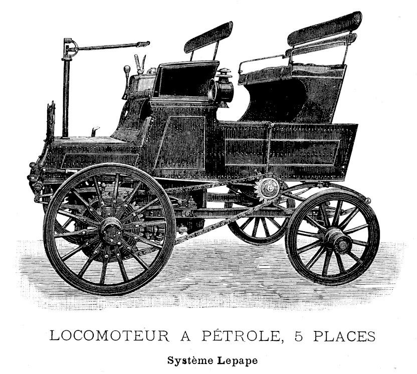
This design originating from Hippolyte Lepape is really one that differs from many of its time. Lepape was more interested in technical innovations than in production. this one, called the Locomoteur captured front-wheel drive with rear-wheel steering. The rear steering was performed with a special linkage The „locomoteur“ didn’t require a gearbox, as it was a continuously variable transmision with friction wheels. How much novelties do You want in a new vehicle, Sir? You name it.

With authorisation of Bibliothèque national francais, gallica.bnf.fr. Text and photos compiled by motorracingistory.com. Translation by Deepl.com
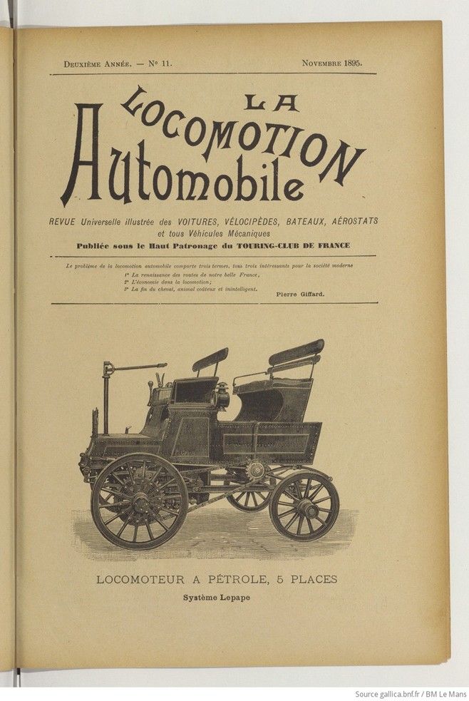
La Locomotion Automobile, Vol. 2, No. 11, November 1895
Oil Locomotor, system Lepape
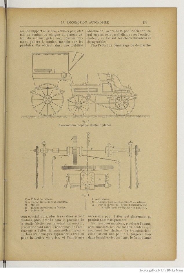
Mr. Lepape’s tractor can be used on its own as a station wagon by fitting the special seat shown at the rear of Fig. 1; it can be hitched to any type of two- or four-wheeled vehicle by simply removing the front axle. The side panels form a reservoir for the water used to cool the engine. Contrary to what is generally seen, the front wheels are driven, while the rear wheels are steered. The lower frame, consisting of two U-shaped steel side members, supports the engine by means of rubber coils to dampen vibrations. For the same reason, this frame rests on the front and rear axles via wooden and rubber blocks, while the car itself rests on it via a wooden chassis and leaf springs, thus achieving complete independence between the engine and the car, which then behaves like an ordinary vehicle.
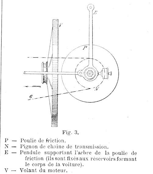
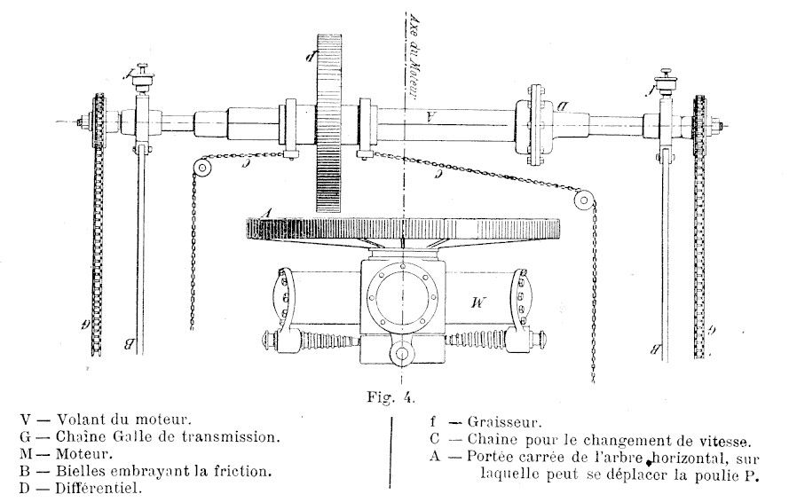
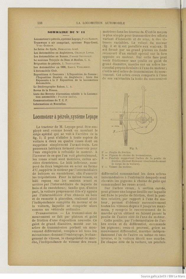
Transmission. — Motion is transmitted by a newly designed friction plate and roller. This large-diameter roller, mounted on a transmission shaft carrying a differential movement, replaces all the mechanisms providing the clutch, gear change, speed change, and independent speed of the drive wheels when cornering. This is the simplest way to transmit forces of varying intensity and direction at variable speeds. The engine flywheel (Figs. 3 and 4) is parallel to the axles. It consists of a large cast iron plate covered with a special coating on the side opposite the engine. A large-diameter pulley or roller, mounted on a horizontal shaft perpendicular to the engine axis, can rub against this side; this is the only transmission shaft. This hollow shaft has, at one end, the differential gearbox controlling the two intermediate shafts, at the ends of which are keyed the chain sprockets that drive the front wheels.
A long sleeve slides onto the square-section hollow shaft, to which the friction pulley is attached. The relative position of this pulley in relation to the motor shaft allows all speeds from 0 to maximum to be obtained in succession, including reverse, which is achieved by moving the pulley to the other side of the motor shaft.
This pulley, via the hollow shaft and the differential, controls the pinions; thanks to the differential movement, these can operate independently of each other or even in opposite directions if the car is cornering. On each side of the car, a pendulum supports the shaft, which can be brought into contact with or moved away from the motor flywheel thanks to the ball bearing bushings mounted on the pendulums. This provides absolute mobility of the friction pulley shaft, ensuring parallelism with the drive axle and avoiding harmful and unpleasant shocks.
The greater the starting or running effort, the tighter the chains will be, and the greater the pressure of the friction pulley on the engine flywheel, thus proportioning the clutch grip to the effort to be transmitted. The driver therefore only has to approach the friction to engage it, and the grip necessary to prevent slippage occurs automatically.
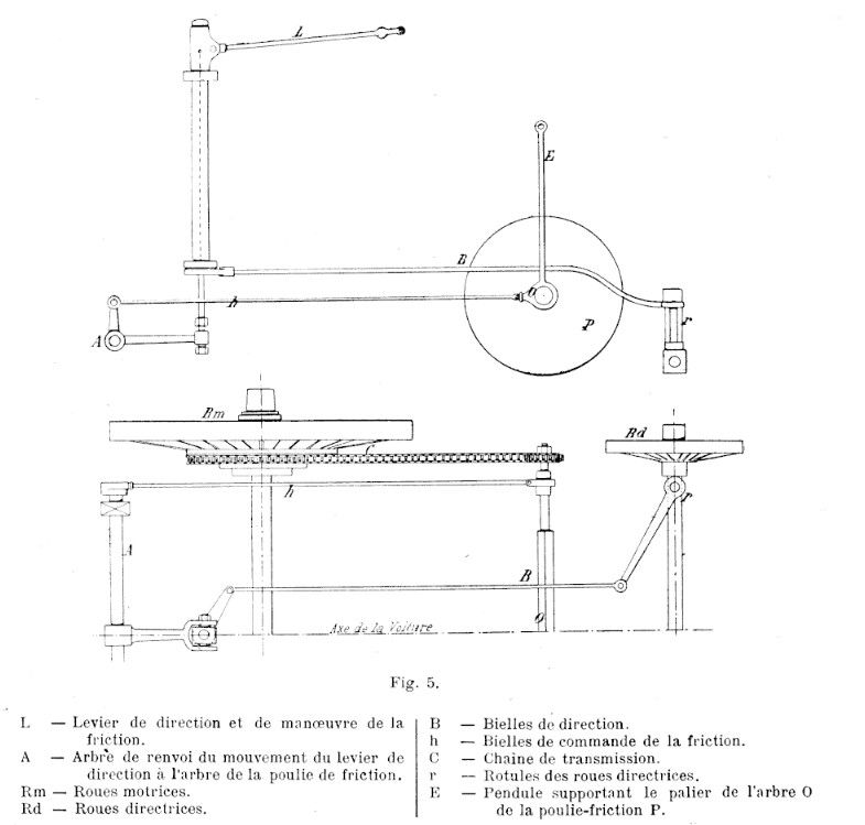
The drive wheels, located at the front, are fitted with toothed rings that receive the drive chains; they carry a wooden groove pulley in which the spring blade brake is housed. The rings and pulleys are bolted to the center of the wheel spokes, to which they give rigidity (Fig. 5).
Driving the locomotive. — The rear wheels, mounted on pivots, are steering wheels; they are operated, by maneuvering to the right or left, by a lever that the driver holds in his left hand. This same lever can also swing up and down. Lowering it brings the friction pulley closer to the engine flywheel, thereby engaging the clutch; raising it, on the other hand, disengages the clutch and, as this movement continues, the pulley rubs against a crossbar, which stops the vehicle by pulling on the chains, whose movement is thus slowed down.
With his right hand, the driver operates another lever which, by means of a small chain, moves the friction pulley on its shaft; we have seen that this allows variations in speed and even a change in direction. With the pedal, the driver operates the additional emergency brake required by police regulations.
If the locomotor were required to tow heavy loads at low speed, small sprockets could be quickly substituted for those placed at the end of the friction pulley shaft.
To the driver’s right are the engine control valves and accessories, located in a box on the seat.
Engine. – We recently mentioned, when studying the Lepape engine (which is used in the locomotor), that it runs at 400 revolutions per minute and weighs only 50 kilos per horsepower. The ignition is electric to avoid any risk of fire. The fuel consumption is 4 liters per hour for a 6-horsepower engine (commercial mineral gasoline).
The whole unit (tractor and engine) seems to us to have been designed with great care; there are several truly ingenious ideas here. We will keep our readers informed of the performance of this interesting tractor, which we will no doubt see competing in the next car race.
Paul Sarrey, Ingénieur.
Photos.
Fig. 1 OIL LOCOMOTOR, 5 SEATS System Lepape
Fig. 2. Locomotor Lepape, coupled, 8 places

Photos.
P — Friction pulley.
N — Transmission chain sprocket.
E — Pendulum supporting the friction pulley shaft (they are attached to the tanks forming the body of the car).
V — Engine flywheel.
Fig. 4.
V — Engine flywheel. G — Galle transmission chain. M— Engine. B — Coupling rods engaged by friction. D — Differential. f — Grease nipple. C — Chain for changing gears. A — Square bearing of the horizontal shaft, on which the pulley P can move.
Fig. 5
L — Steering and friction control lever.
A — Shaft transmitting the movement of the steering lever to the friction pulley shaft.
Rm — Drive wheels.
Rd — Steering wheels.
B — Steering connecting rods.
h — Friction control connecting rods.
C — Transmission chain.
r — Steering wheel ball joints.
E — Pendulum supporting the bearing of shaft O of friction pulley P.
_____Vehicle centerline______