


Seven years after the 1913 introduction of the Rudge-Whithworth central wheel assembling and locking device, a short commentary is given in this article, highlighting its general succes in the automotive world (translation included).

Avec l’authorisation du Conservatoire numérique des Arts et Métiers (Cnum) – https://cnum.cnam.fr
Texte et photos compilé par motorracinghistory.com
La Vie Automobile 16e Année. — N° 720. – Samedi 25 décembre 1920.
La Roue détachable RUDGE-WITWORTH
Le dispositif actuel de détachabilité de la roue Rudge-Whitworth a réuni les suffrages de la plupart des constructeurs de grandes marques : c’est qu’en effet, par l’absence de tous ressorts, pièces de sûreté à crans, etc., il supprime les inconvénients inhérents à ces différents systèmes, tels que : rupture de ressorts, intrusion d’un corps étranger, usure des crans, etc., qui empêchent le fonctionnement du verrouillage.
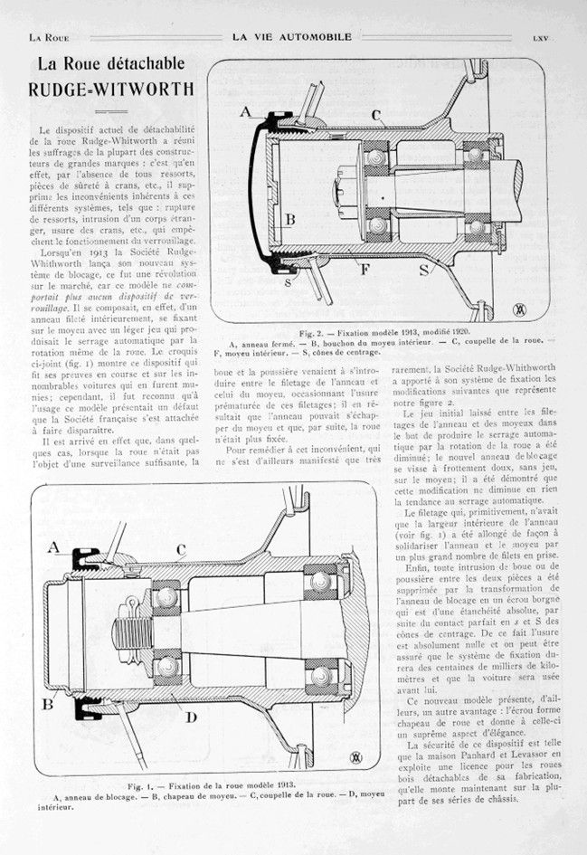
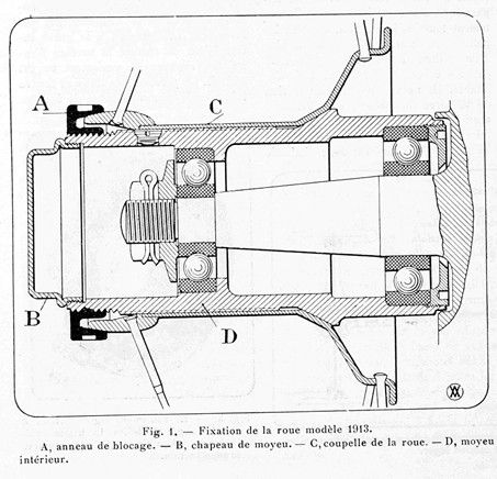
Lorsqu’en 1913 la Société Rudge-W’hithworth lança son nouveau système de blocage, ce fut une révolution sur le marché, car ce modèle ne comportait plus aucun dispositif de verrouillage. Il se composait, en effet, d’un anneau fileté intérieurement, se fixant sur le moyeu avec un léger jeu qui produisait le serrage automatique par la rotation même de la roue. Le croquis ci-joint (fig. 1) montre ce dispositif qui fit ses preuves en course et sur les innombrables voitures qui en furent munies ; cependant, il fut reconnu qu’à l’usage ce modèle présentait un défaut que la Société française s’est attachée à faire disparaître.
Il est arrivé en effet que, dans quelques cas, lorsque la roue n’était pas l’objet d’une surveillance suffisante, la boue et la poussière venaient à s’introduire entre le filetage de l’anneau et celui du moyeu, occasionnant l’usure prématurée de ces filetages ; il en résultait que l’anneau pouvait s’échapper du moyeu et que, par suite, la roue n’était plus fixée.
Pour remédier à cet inconvénient, qui ne s’est d’ailleurs manifesté que très rarement, la Société Rudge-Whithworth a apporté à son système de fixation les modifications suivantes que représente notre figure 2.
Le jeu initial laissé entre les filetages de l’anneau et des moyeux dans le but de produire le serrage automatique par la rotation de la roue a été diminué ; le nouvel anneau déblocage se visse à frottement doux, sans jeu, sur le moyeu ; il a été démontré que cette modification ne diminue en rien la tendance au serrage automatique.
Le filetage qui, primitivement, n’avait que la largeur intérieure de l’anneau (voir fig. 1) a été allongé de façon à solidariser l’anneau et le moyeu par un plus grand nombre de filets en prise.
Enfin, toute intrusion de boue ou de poussière entre les deux pièces a été supprimée par la transformation de l’anneau de blocage en un écrou borgne qui est d’une étanchéité absolue, par suite du contact parfait en s et S des cônes de centrage. De ce fait l’usure est absolument nulle et on peut être assuré que le système de fixation durera des centaines de milliers de kilomètres et que la voiture sera usée avant lui.
Ce nouveau modèle présente, d’ailleurs, un autre avantage : l’écrou forme chapeau de roue et donne à celle-ci un suprême aspect d’élégance.
La sécurité de ce dispositif est telle que la maison Panhard et Levassor en exploite une licence pour les roues bois détachables de sa fabrication, qu’elle monte maintenant sur la plupart de ses séries de châssis.
Photos/clichés.
Fig. 1. — Fixation de la roue modèle 1913.
A, anneau de blocage. — B, chapeau de moyeu. — C, coupelle de la roue. — D, moyeu intérieur.
Fig. 2. — Fixation modèle 1913, modifié 1920.
A, anneau fermé. — B, bouchon du moyeu intérieur. — C, coupelle de la roue. — F, moyeu intérieur. — S, cônes de centrage.
With authorisation of the Conservatoire numérique des Arts et Métiers (Cnum) – https://cnum.cnam.fr
Text and fotos compiled by motorracinghistory.com – Translation by Deepl.com
The RUDGE-WITWORTH detachable wheel
The current Rudge-Whitworth detachable wheel system has won the approval of most major manufacturers: this is because, with no springs, safety catches, etc., it eliminates the disadvantages inherent in these different systems, such as broken springs, foreign objects getting stuck in the mechanism, wear and tear on the catches, etc., which prevent the locking mechanism from working properly.
When the Rudge-Whitworth Company launched its new locking system in 1913, it was a revolution in the market, as this model no longer had any locking device. It consisted of an internally threaded ring, which was attached to the hub with a slight play that produced automatic tightening through the rotation of the wheel itself. The attached sketch (fig. 1) shows this device, which proved its worth in racing and on the countless cars that were equipped with it; however, it was recognized that in use this model had a flaw that the French company set out to eliminate.
In some cases, when the wheel was not sufficiently monitored, mud and dust would get between the threads of the ring and those of the hub, causing premature wear of these threads. As a result, the ring could slip out of the hub, causing the wheel to become loose.
To remedy this problem, which occurred only very rarely, Rudge-Whithworth made the following modifications to its fastening system, as shown in Figure 2.
The initial play left between the threads of the ring and the hubs in order to produce automatic tightening by the rotation of the wheel has been reduced; the new release ring screws onto the hub with a smooth friction fit, without play; it has been demonstrated that this modification in no way reduces the tendency for automatic tightening.
The thread, which originally had only the inner width of the ring (see Fig. 1), has been lengthened so that the ring and hub are held together by a greater number of engaged threads.
Finally, any intrusion of mud or dust between the two parts has been eliminated by transforming the locking ring into a cap nut that is completely sealed, thanks to the perfect contact between the centering cones. As a result, there is absolutely no wear and tear, and we can be sure that the fastening system will last for hundreds of thousands of kilometers and that the car will wear out before it does.
This new model also has another advantage: the nut forms a wheel cap and gives the wheel a supremely elegant appearance.
This device is so safe that Panhard et Levassor has licensed it for the detachable wooden wheels it manufactures, which it now fits on most of its chassis series.
Photo captions.
Fig. 1. — 1913 model wheel fastening.
A, locking ring. — B, hub cap. — C, wheel cup. — D, inner hub.
Fig. 2. — 1913 model fastening, modified in 1920.
A, closed ring. — B, inner hub cap. — C, wheel cup. — F, inner hub. — S, centering cones.