


This September 1928 issue of the Journal of the SAE, deals with the up-to-then status of front wheel drive. In all, this very lenghty article comprises of no less that 25 pages, inclusive photograhs. All aspects are discussed; davantages and disadvantages are listed and compared. Almost all known front wheel drives in the US and on the continent are described. As for it’s length, the complete article is divided into four parts; here’s part IV, wishing You an interesting read.


Text and jpegs by courtesy of hathitrust.org www.hathitrust.org, compiled by motorracinghistory.com
Journal of the SAE, Vol. XXIII (23), No. 3, September 1928.
Front-Wheel Drives, Are They Coming or Going? – Part IV
By HERBERT CHASE – M.S.A.E.-Engineer, Erickson Co., Inc., New York City.
SEMI-ANNUAL MEETING PAPER Illustrated with PHOTOGRAPHS AND DRAWINGS
To prevent undue reactions on the steering-mechanism, the point of intersection of the steering-knuckle axis with the road must not be more than 12 to 4 in. from the center line of the tire. With a wheel camber of 3½ deg., a steering-knuckle-pivot side-rake of 3½ deg. gave very satisfactory results and permitted an offset of the steering-knuckle axis of not more than ½ in.
The provisions for a grease-and-dust-tight construction are shown also in Fig. 22. Leather boots were found to have short life.
Steering the front-wheel drive presents two problems which are very satisfactorily met in our construction. To obtain large angles of steering, it is impractical to use a straight tie-rod between the wheels. If placed behind the axle, a tie-rod would interfere with the tire rims and, if placed in front, the arm at the wheel would have to project through the wheel to give the proper relative angles of the two wheels. We use two short cross-links, one to each wheel, which are connected to a horizontal bell-crank at the middle of the vehicle which is in turn linked to the steering-gear. With correct pivot-points at the wheels and bell crank, the proper wheel angles are obtained without interference. The second problem is to compensate for the in-and-out movement of the wheel hubs at bumps and rebounds caused by the radius-arm type of suspension. This is also solved by the double cross-links having properly located centers.
The only British front-wheel-drive passenger-car about which particulars are available is the Alvis, a development of the Alvis racing car. (See Figs. 24 and 25.) In general this design is similar to the Miller and the Marmon designs in America, except that, instead of using a dead axle to connect steering- knuckles, these are supported on four short trans- verse quarter-elliptic springs on each side of the frame, the two in each pair being placed far enough apart in plan view to provide the requisite stiffness against fore-and-aft shocks when the front wheels strike obstacles. Full details concerning this de- sign are not at hand, but the published sketches show what seem to be two independent drag-links, indicating that a dual steering-system is employed. This is in line with experience cited by M. de Lavaud in other designs having independently sprung front wheels. There is no rear axle in the ordinary sense, the wheels being mounted at the ends of radius-arms pivoted to the frame and reacting against short quarter- elliptic springs. This unusual springing at the front and the rear is said to provide unusually easy riding- quality and to enable the car to negotiate turns at a much higher speed than is safe with an ordinary rear- drive car.
ITALA RACING-CAR DESIGN
Published descriptions of this and of several of the other designs referred to subsequently are rather meager in detail. In the Itala design shown in Fig. 26 the casing of the clutch, transmission and differential is bolted to the front end of the engine. The two transverse driveshafts from the differential have universal-joints at each end, that at the inner end providing for necessary end-motion. Above the driveshaft at each side is a very broad quarter-elliptic cantilever spring, the ends of which are said to be mounted between rubber blocks. As will be seen from Fig. 26, this spring is enclosed in a metal housing designed to protect it and to reduce wind resistance without interfering with its free motion. Connection between this casing and differential housing is made by a broad rubber-band. A similar construction is used below the driveshaft, except that in place of the cantilever spring there is a rigid beam with a spring mounting at each end. An apparently similar structure is used in place of a conventional rear axle.
TWO FRENCH FRONT-WHEEL DRIVES
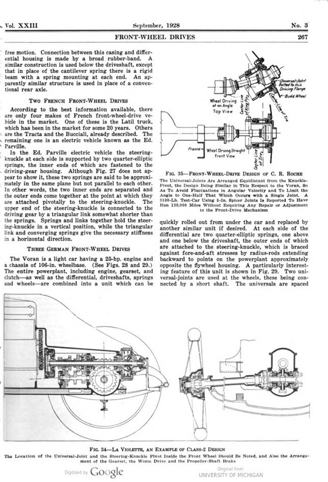
According to the best information available, there are only four makes of French front-wheel-drive vehicle in the market. One of these is the Latil truck, which has been in the market for some 20 years. Others are the Tracta and the Bucciali, already described. The remaining one is an electric vehicle known as the Ed. Parville.
In the Ed. Parville electric vehicle the steering-knuckle at each side is supported by two quarter-elliptic springs, the inner ends of which are fastened to the driving-gear housing. Although Fig. 27 does not appear to show it, these two springs are said to be approximately in the same plane but not parallel to each other. In other words, the two inner ends are separated and the outer ends come together at the point at which they are attached pivotally to the steering-knuckle. The upper end of the steering-knuckle is connected to the driving gear by a triangular link somewhat shorter than the springs. Springs and links together hold the steering-knuckle in a vertical position, while the triangular link and converging springs give the necessary stiffness in a horizontal direction.
THREE GERMAN FRONT-WHEEL DRIVES
The Voran is a light car having a 25-hp. engine and a chassis of 106-in. wheelbase. (See Figs. 28 and 29.) The entire powerplant, including engine, gearset, and clutch – as well as the differential, driveshafts, springs and wheels – are combined into a unit which can be quickly rolled out from under the car and replaced by another similar unit if desired. At each side of the differential are two quarter-elliptic springs, one above and one below the driveshaft, the outer ends of which are attached to the steering-knuckle, which is braced against fore-and-aft stresses by radius-rods extending backward to points on the powerplant approximately opposite the flywheel housing. A particularly interesting feature of this unit is shown in Fig. 29. Two universal-joints are used at the wheels, these being connected by a short shaft. The universals are spaced equidistant from the steering-knuckle pivot, an arrangement said to transmit uniform angular motion to the wheel. The outer end of the axle shaft is supported in a spherical housing or bearing. The short shaft that connects the two universal-joints floats.
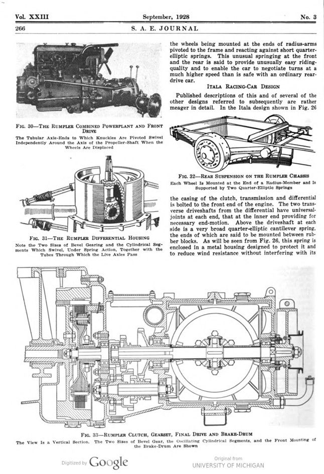
An unusual, and what seems to me to be an unnecessarily complicated, construction is that employed by Dr. Edwin Rumpler in a 50-hp. front-wheel-drive car. This drive, which is pictured in Figs. 30 to 33, is described by P. M. Heldt (See Automotive Industries, June 4, 1927, p. 831), as follows:
“The Rumpler axle construction is unusual in that the axle ends to which the knuckles are pivoted are carried by tubular members surrounding the drive shafts. These tubular members are not fastened rigidly into the central housing but have independent pivotal motion around the fore-and-aft longitudinal axis, or the axis of the propeller-shaft. This is made possible by mounting the differential gear on the propeller-shaft instead of on the driven shafts, and it is really around the axis of the differential gear that the two axle-halves swivel. Each axle shaft has its own bevel drive-gear, which is driven by a separate bevel pinion on one of the differential side-gears. To prevent interference between the two sets of bevel drive-gears, they are made different in size. The two axle-tubes are fitted into sectors located on the inside of the cylindrical housing over the differential. These sectors are comparatively wide and, in addition to the axle-tubes, two brace-rods are anchored in each to give the axle the necessary horizontal stiffness.
The axle tube ends in a spherical housing which encloses a universal-joint connecting to the knuckle-shaft, and the joint evidently is working only when, in steering, the wheels are deflected from the straight- ahead position.
At the front, the frame is supported on the axle ends by two pairs of transverse semi-elliptic springs. The propeller-shaft extends entirely through the drive-gear housing and carries at its forward end a large brake-drum to which a pair of contracting brake-shoes can be applied. The powerplant and front axle form a unit that can be readily replaced by another unit. “
The longitudinal section view of the Rumpler clutch, gearset and differential in Fig. 33 shows also an arrangement of brake in front of the gearset which is one of the optional positions in which such a brake can be placed. It provides braking on the front wheels with- out locating the brake-drums on the wheels themselves and also equalizes the braking action. This is an interesting contrast to the Miller and the Marmon designs in which the brake-drums are placed on the driveshafts at each side of the differential housing.
Other examples of front-drive designs are shown and described in Figs. 34 to 38, being of the La Violette, the C. R. Roche and the Hamlin types.
UNIVERSAL-JOINT DESIGN
One of the important considerations in designing a front-wheel drive is to provide universal-joints that will give the desired uniform angular velocity. In this connection, I quote again from Mr. Heldt’s paper“, as follows:
“Of the two universals in each driveshaft, the one near the central housing has to take care only of the angularity due to spring play. Fortunately, the vertical play of the front spring is not very great, being limited to about 2 in. on each side of the normal position. Moreover, spring play does not affect the parallelism between the differential shafts and the knuckle- shafts, and the angle between the differential-shaft and the axle-shaft is always the same as the angle between the axle-shaft and the knuckle-shaft; hence, the speed fluctuations created by one joint will be neutralized by the other.
It is different, however, with respect to the angularity between shafts due to steering motion. The angle of the steering-spindle with the axle may exceed 30 deg.; in fact, it may reach 40 deg. and, for such angles, there would be extreme fluctuations in the speed of the driven member if the speed of the driving member were constant. For an angle of 30 deg., for instance, the speed of the driven shaft would fluctuate through a range equal to 29 per cent of its mean speed.
Actually, of course, neither the driving nor the driven shaft would run at constant speed; but one would accelerate and the other would at the same time decelerate, and both would be subjected to very great stresses as a result of these accelerations and decelerations because of the heavy masses connected with them. It would therefore be desirable to use at the knuckle end of the axle-shaft either a type of universal-joint that is free from these periodic fluctuations, or else two joints located close together and symmetrically on opposite sides of the knuckle-pin axis when the wheel is in the straight-ahead position. Then, if the wheel is swung around for steering, each of the two adjacent universals will assume the same angularity, and the fluctuations in the transmission ratio due to the two joints will cancel out”.
With Mr. Heldt’s foregoing remarks in mind, it is interesting to note what steps have been taken in various designs to meet the conditions here outlined. One is to employ a type of universal-joint such as the Weiss, which provides a uniform angular velocity regardless of the layout employed. Much the same result is attained by the construction employed in the Healey- Aeromarine design, and it is claimed in the Tracta design which is, in effect, a double universal-joint. In the Voran design two joints are employed and they are placed equidistant from the steering-knuckle axis so that, it is contended, fluctuations of the angular velocity are cancelled out; but this contention seems to require qualification if the universals are of the conventional type with yokes connected to pins at right angles. In this case the variations in angular velocity cancel out when the two joints make equal angles with the shaft connecting them, as they seem to do in the Voran design. Apparently, however, the inner of the two joints in the wheel will impose a fluctuating velocity upon the shaft connecting it to the differential; but, since the angle at this joint is only half that through which the wheel is turned, the effect may not be serious.
Fig. 39 shows front-drive universal-joints of a type used in approximately 70 motorcoaches of 51 to 70- passenger capacity which have been operated millions of miles in Chicago. On the basis of this experience G. A. Green, of the General Motors Truck Corporation, says:
No thoroughly satisfactory design has yet been developed, which provides a driving shaft to each front wheel with two universal-joints incorporated. Any such arrangement results in undue tire wear, due to constant change in the angular velocity of the universal-joints.
SUMMARY
Concerning the future of front-wheel drives, we have seen that they present many advantages and that there is good ground for the view that the advantages outweigh the disadvantages; but it does not follow as a necessary corollary that front-drive cars will become the popular type or even that they will be adopted soon by many manufacturers. It is known, however, that at least three or four companies, including one or two prominent makers, are greatly interested in this type of drive and either have experimental cars well advanced or are planning to build them. One company is reported to have acquired the Miller patent-rights on front-wheel drives. It would not be surprising to see two or more front-drive cars offered at next year’s shows if, indeed, some such designs are not marketed before that time.
Photo captions.
Page 252.
FIG. 1-BOLLSTROM TRUCK FRONT DRIVE
This Drive Is Similar to Some Rear Drives Except for the Steering-Knuckles and the Universal-Joints. The Entire Axle-Housing and Internal-Gear Drive Constitute Unsprung Weight, but They Seem To Provide a Substantial Construction for Truck Applications
FIG. 2-FRONT AXLE USED IN THE COLEMAN FOUR-WHEEL-DRIVE TRUCK
The Novel Feature of This Design Is the Universal-Joint Inside the Wheel. The Wide Spread of the Yoke Bearings Reduces the Bearing Pressures at These Points. The Axes of the Yoke Bearings and the Steering-Pivot Are in the Same Plane
Page 253.
FIG. 3-COLEMAN FRONT-AXLE PARTS / FIG. 4 COLEMAN UNIVERSAL-JOINT
The Very Large Diameter of the Universal-Joints Is Evident. This Is an Example of Class-1 Design in Which a More or Less Conventional Rear-Axle Type Has Been Adapted To Perform the Steering as Well as Driving Functions. The Complete and Rather Heavy Assembly Is Unsprung
Page 254.
FIG. 5-BUCCIALI CHASSIS FRONT-SPRING SUSPENSION / FIG. 6-FRONT VIEW OF MILLER FRONT AXLE
Part of the Bow-Shaped Dead-Axle and the Differential Cover Are Removed To Show the Arrangement of the Gearing. Some of These Axles Have Two-Speed and Some Have Three-Speed Gearsets
Page 255.
FIG. 7-MARMON RACING CAR WITH A RUCKSTELL AXLE
This Design Is Typical of the Designs in Class 2 in Which the Steering-Knuckles Are Joined and Positioned by a Dead Axle, but in Which the Differential, the Brakes and the Gearset Are Sprung, Being Mounted in a Unit with the Engine
FIG. 8-RUCKSTELL GEARSET AND DIFFERENTIAL USED ON THE MARMON RACING CAR
It Should Be Noted That the Gearset Is Placed Beside the Differential. With This Arrangement There Need Be No Material Increase in Over-All Length of the Powerplant, and the Engine Need Be Placed Little, if Any, Farther Aft Than with Rear-Wheel Drive
FIG. 9-SPRING SUSPENSION ON THE MARMON RACING CAR
The View Shows One of the Two Pairs of Quarter-Elliptic Springs Which Support the Front of the Chassis. The Position of the Brake-Drum Should Be Noted; It Is Accessible and Is in Good Position To Assure Proper Cooling, Yet It Constitutes Part of the Sprung Weight
Page 256.
FIG. 10-WEISS UNIVERSAL-JOINT AND SHAFT CONSTRUCTION
This Drive Is Similar to That Used in the Marmon Racing Car and in Experimental Front-Drive Cars Now Undergoing Test, The Universal-Joints Are Designed To Give Uniform Angular Motion. The Inner Universal-Joint Permits 1 In. of Axial Motion on a Rolling Contact; Hence, No Sliding Spline Is Required (End Motion = 1″ Maximum Angle = 15°)
Page 257.
FIG. 11-WEISS FRONT-DRIVE UNIVERSAL-JOINTS AND SHAFT ASSEMBLY
The Ball Raceways of the Inner Joint Are Straight; Those in the Outer Joint Are Curved and Permit Angular Deflections in Excess of 30 Deg
FIG. 12-FRONT AXLE OF WALTER FOUR-WHEEL-DRIVE TRUCK In This Design the Dead-Axle Center Joining and Positioning the Steering-Knuckle Is Placed below the Differential, Which Is Mounted on the Frame. The Second Reduction Is by Internai Gear and Pinion within the Wheel; Hence, the Torque on the Universal-Joints Is Less Than in Single-Reduction Designs Trans- mitting the Same Power
Page 258.
FIG. 13-THE TRACTA, A RECENT FRENCH DESIGN
Unlike the Other Designs in Class 2, This Has a Dead Axle That Is Sprung. The Wheels and Parts Immediately Adjacent to or Inside Them Constitute the Whole Unsprung Weight. The Springs Are of Helical Type and Are Located Inside Cylindrical Steering- Knuckle-Pivot Guides
FIG. 14-PARTS OF THE TRACTA FRONT-WHEEL DRIVE
The Universal-Joints Are Said To Give Uniform Angular Velocity
Page 259.
FIG. 15-SECTIONAL VIEW OF THE KAMM FRONT DRIVE
The Steering-Knuckle Is Guided by Brackets Attached to the Stiff Frameless Body. The Wheels Are Individually Sprung. In Principle, the Construction Is Similar to That of the Tracta, but the Structure Itself Is Very Different. Both Designs Have Coil Springs above the Steering-Knuckles
Page 260.
FIG. 16-FRONT-DRIVE ASSEMBLY OF THE UPPERCU COACH
This Design Was Used on Early Models. The Steering-Knuckles Were Connected to the Chassis by the Heavy Transverse Spring and Hinged A-Shaped Links. The Central Housing Is Carried on the Frame. The Novel Steering-Layout Should Be Noted
FIG. 17-FRAME OF THE EARLY FORM OF UPPERCU COACH
The Sub-Frame Carries the Powerplant and Driving-Gear Assembly. It Is Made So As To Be Quickly and Easily Detached after Loosening Two Bolts, One of Which Is Shown in the Drawing at the Right
Page 261.
FIG. 18-NOVEL METHOD OF MOUNTING REAR WHEELS ON THE UPPERCU COACH
The Wheel-Spindle Is Carried at the Rear End of the Box-Section Radius-Arm Which Is Pivoted to the Frame. There Is No Rear Axle in the Ordinary Sense of That Term
FIG. 19-HEALEY-AEROMARINE POWERPLANT AND FRONT DRIVE
The Novel Form of Springing Which Takes the Place of the Transverse Spring For- merly Employed on the Uppercu Coach Should Be Noted: Also, the Location of the Gearset, the Clutch and the Fan. The Knuckles Are Positioned by the Links Hinged to the Frame. The Strut and the Secondary Link Which Transmit Wheel Deflections to the Horizontal Helical Spring Are Evident
Page 262
FIG. 20-HEALEY-AEROMARINE CLUTCH, GEARSET, AND WORM DRIVE-GEARS
The Flywheel at the Left Drives, Through a Flexible Coupling, a Propeller-Shaft Which Runs Through the Hollow Worm and Gearset Shafts to the Clutch Attached to the Fan at the Right. Thence, the Drive Is Back Through a Fuller Gearset to the Worm in Conventional Fashion. Part of the Steering Linkage Is Mounted below the Gearset FIG. 21-HEALEY-AEROMARINE FRONT LINKAGE
The Linkage Takes the Place of a Front Axle. Upward Displacement of the Wheel Causes the Knuckle, the Upper End of Which Is Supported by the Lower Link, To Move Upward Also. The Strut Transfers This Movement to the Vertical Link, Which Bears Against the Horizontal Helical Spring. The Helical Spring Reacts Through a Similar Linkage to the Other Knuckle. The Small Shaft Carries Rubber Blocks or Bumpers Which Prevent Excessive Motion
Page 263.
FIG. 22. HEALEY-AEROMARINE FRONT-WHEEL, STEERING-KNUCKLE, AND UNIVERSAL-JOINT ASSEMBLY
This Universal-Joint Permits the Wheel To Be Cramped Through an Angle of 53 Deg. without Variation in Uniform Angular Velocity
FIG. 23-HEALEY-AEROMARINE STEERING-LINKAGE
The Cross-Link or Tie-Rod Is Made in Two Parts To Avoid Interference with the Wheels, Which Have a 53-Deg. Steering-Angle, and To Accomplish Other Purposes as Explained in the Text
Top View Center Line of Bus Center Line of Wheel Drag-Link Center Line of Worm Wheel Center Line of Wheel Front. View Turning Point Center Line of Joint Wheel Center
Page 264.
FIG. 24-THE ALVIS, A BRITISH DESIGN
The Two Drag-Links of the Steering-System Indicate Some Form of Dual Steering-Control Such As Is Considered Desirable with Independently Sprung Front Wheels
FIG. 25-PARTS OF THE ALVIS DESIGN This Is a Typical Example of Class-3 Construction in Which the Dead Axle Is Replaced by Springs That Position the Knuckles and Also Support the Front End of the Chassis. Brake-Drums Are Located at Each Side of the Differential. In Place of the Rear Axle Are Radius-Members upon Which the Wheel Spindles Are Supported
FIG. 26-ITALA RACING-CAR DESIGN
This Is Another Example of the Type of Designs Grouped in Class 3. In This Case the Transverse Quarter-Elliptic Springs above the Live Axle Are Fairly Wide at Their Inner Ends and Are Mounted between Rubber Blocks. Links Are Used Below the Axle. The Sheet-Metal Coverings Are Designed To Reduce Wind Resistance
Page 265.
FIG. 27-THE ED. PARVILLE DESIGN, A FRENCH ELECTRIC FRONT-DRIVE
The Two Quarter-Elliptic Springs Are Not in the Same Vertical Plane Inner Ends Are Separated As Seen in Plan View and the Outer Ends Come Together at the Steering-Knuckle. At the Top the Knuckle Is Pivoted to the Outer End of a Triangular Link Which Is Hinged to the Frame
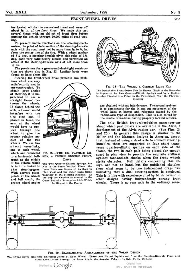
FIG. 28-THE VORAN, A GERMAN LIGHT CAR
The Detachable Front-Drive Unit Is Shown. Each of the Knuckles Is Supported by Two Quarter-Elliptic Springs and by a Radius-Member Pivoted to a Point on the Powerplant Near the Flywheel Housing
FIG. 29-DIAGRAMMATIC ARRANGEMENT OF THE VORAN DESIGN
The Front Drive Has Two Universal-Joints at Each Wheel. These Are Placed Equidistant from the Steering-Knuckle Pivot and, Since Each Drives Through the Same Angle, the Angular Velocity Is Said To Be Uniform
Page 265.
FIG. 30-THE RUMPLER COMBINED POWERPLANT AND FRONT DRIVE
The Tubular Axle-Ends to Which Knuckles Are Pivoted Swivel Independently Around the Axis of the Propeller-Shaft When the Wheels Are Displaced
FIG. 31-THE RUMPLER DIFFERENTIAL HOUSING
Note the Two Sizes of Bevel Gearing and the Cylindrical Segments Which Swivel, Under Spring Action, Together with the Tubes Through Which the Live Axles Pass
FIG. 32-REAR SUSPENSION ON THE RUMPLER CHASSIS
Each Wheel Is Mounted at the End of a Radius-Member and Is Supported by Two Quarter-Elliptic Springs
FIG. 33-RUMPLER CLUTCH, GEARSET, FINAL DRIVE AND BRAKE-DRUM
The View Is a Vertical Section. The Two Sizes of Bevel Gear, the Oscillating Cylindrical Segments, and the Front Mounting of the Brake-Drum Are Shown
Page 267.
FIG. 34-LA VIOLETTE, AN EXAMPLE OF CLASS-2 DESIGN
The Location of the Universal-Joint and the Steering-Knuckle Pivot Inside the Front Wheel Should Be Noted, and Also the Arrangement of the Gearset, the Worm Drive and the Propeller-Shaft Brake
FIG. 35-FRONT-WHEEL-DRIVE DESIGN OF C. R. ROCHE
The Universal-Joints Are Arranged Equidistant from the Knuckle- Pivot, the Design Being Similar in This Respect to the Voran, So As To Avoid Fluctuations in Angular Velocity and To Limit the Angle to One-Half That Which Occurs with a Single Joint. A 3100-Lb. Test-Car Using 5-In. Spicer Joints Is Reported To Have Run 130,000 Miles Without Requiring Any Repair or Adjustment to the Front-Drive Mechanism
(Wheel Driving at an Angle Top View – Center Line of King Pin – Frame – Wheel Driving Straight Front View – Center Line of Tire – Universal-Joint Bolted to Hub Driving Flange – Budd Wheel – Center Line of Tire)
Page 268.
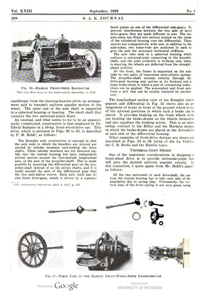
FIG. 36-HAMLIN FRONT-DRIVE RACING-CAR
This Car Was Seen at the Indianapolis Speedway in 1926
FIG 37-PARTS USED IN THE HAMLIN FRONT-WHEEL-DRIVE PASSENGER-CAR
Page 269.
FIG. 38-THE 1928-MODEL HAMLIN FRONT-WHEEL-DRIVE TEST-CHASSIS
FIG. 39-TYPE OF FRONT-DRIVE UNIVERSAL-JOINTS USED IN CHICAGO MOTORCOACHES