


This article from the well-known French technicalist-journalist Charles Faroux extensively and meticuously describes the many new features of the Peugeot Charlatans‘ designed and developed small 7.6 liter capacity, 4-cylinder, hemi-head, 4-valve, doube overhead camschaft Grand Prix engine. With this engine, being the very precursor for many more engines still to come over decades, Peugeot won the 1912 French Grand Prix. Not only the engine, still more characteristics of the drivetrain and vehicle architecture are highlighted here. In the months after that 1912 Grand Prix, several more magazines would publish on this remarkable car/engine combination.
With authorisation of Conservatoire numérique des Arts et Métiers (Cnum) – https://cnum.cnam.fr
Text and photos compiled by motorracinghistory.com – Translation by deepL.com
La Vie Automobile Volume 12. — N° 570. – Saturday August 31, 1912.
The Grand Prix winner
After every major motor race, we receive numerous letters from our subscribers asking us to describe the winning car.
Although we understand and share this very legitimate curiosity, we are unfortunately not always able to satisfy them. The winning manufacturer is generally not keen to reveal the secrets of the features that earned them victory.
This year, however, in response to the great desire of many of our subscribers to learn about the valiant machine to which we owe the triumph of our colors, we were able to obtain permission from Peugeot to present it to our readers with a few details, and its friendly driver Boillot kindly agreed to provide us with the necessary documents. Of course, we will not disclose certain details and data, as our readers will understand how legitimate it is for everyone to retain the fruits of their research.
We would like to express our sincere thanks to Peugeot for the permission they have so kindly granted us, as well as to Boillot, who has provided us with such helpful documentation. Charles Faroux.
To get an engine with a bore of 110 mm and a stroke of 200 mm to produce 175 horsepower, to build a car weighing 980 kg with this engine, to reach a speed of nearly 190 kilometers per hour with this machine; and, after thirteen hours of fierce competition against rivals twice its size, triumph in a hard-fought battle over a distance of 1,540 kilometers, thus demonstrating that consistency goes hand in hand with speed, and that the machine is as robust as it is fast; this certainly demonstrates a high level of virtuosity in the design and construction of a car and a perfect mastery of the technology.
The factories that have achieved such results can be justifiably proud, especially when this first victory is followed by a second that is no less brilliant. Indeed, we know that Boillot’s Peugeot, the glorious 22 from Dieppe—since that is the car in question—has just won the Ventoux hill climb in 17 min. 45 seconds, masterfully beating the previous record of 18 m.41s, which had stood for three years.
The study of the solutions that contributed to these triumphs is of the utmost interest. That is why we are pleased to present our readers with a detailed description of this beautiful racer.
The chassis of this car is, of course, made of stamped steel, narrowed at the front and centered at the rear to avoid the axle. The entire assembly, including the engine, clutch, and gearbox, rests on a subframe or cradle, which is attached to the chassis by only three perfectly lubricated spherical ball joints. The engine assembly is thus completely isolated from the inevitable chassis distortion, thereby avoiding any additional jamming or friction.
As mentioned above, the engine is a 110×200 four-cylinder unit. It runs at approximately 2,200 revolutions per minute, giving a linear piston speed of 14 m, 60.
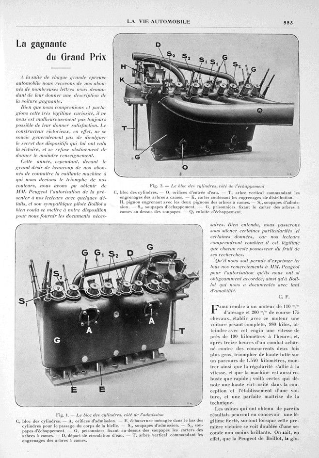
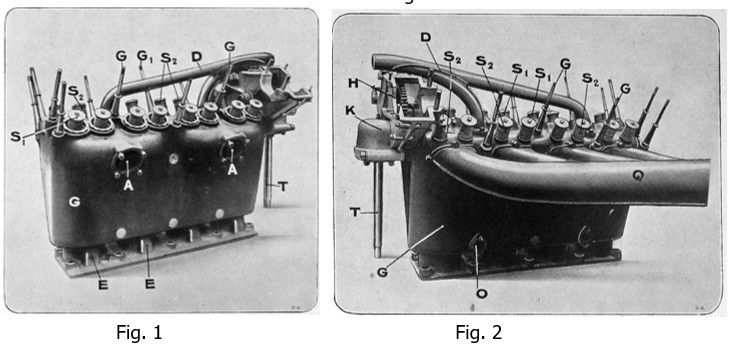
The cylinders (fig. 1 and 2) are cast in a single block with the common water jacket, in which they are separated. This provides excellent cooling and absolutely uniform expansion.
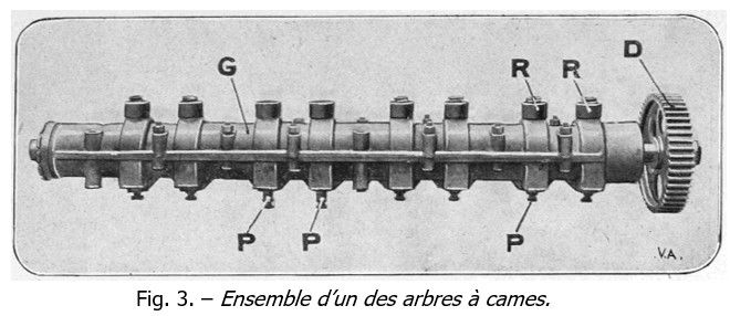
The cylinder heads are hemispherical and the valves are positioned at 45°. In order to provide a large gas passage section and allow the engine to breathe freely, each cylinder has four valves, two intake valves measuring 60 millimeters and a lift of 11. Their control method is particularly original. We did not encounter the usual rocker arms here, which might have caused some problems at the high speeds this engine was designed to reach. Each row of valves is topped by a casing similar to the one shown in Fig. 3, containing a camshaft. These two camshafts are controlled in the casing, which can be seen open at the top of the cylinder block in Figs. 1 and 2, and driven by means of an angle drive by a vertical shaft located at the front of the engine. Each shaft has eight cams, each acting inside an eccentric bearing the tappet and forming a single piece with it. As the tappet does not carry a roller, the roller is carried by the end of the cam. It is clear that the shape of the eccentric must have been the subject of lengthy studies, as it is partly responsible for the timing adjustment. These tappets, which are adjustable by means of a nut, are also returned by a spring visible above each of them when the cam stops pushing them down. They are positioned in line with the valve stems and act directly on them.
The pistons are made of steel and, together with their pins and rings, weigh only 920 grams. The pin is not fixed in the piston bosses, as is usually the case, while the connecting rod pivots on it; on the contrary, it is fixed to the connecting rod and rotates without its bronze bushings carried by the piston bosses. This device, used on some American cars, is advantageous in that it is much easier to secure the pin to the connecting rod safely than in the piston bosses. However, a pin that becomes loose in the bosses quickly wears them down and can cause the piston to break. It is easy to see that this is very important in a high-speed engine such as this one.
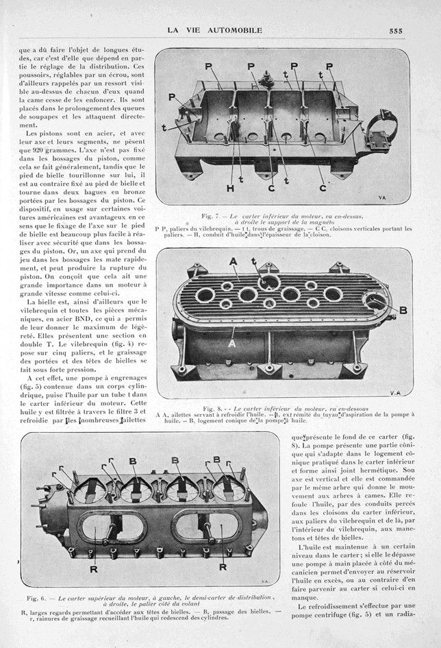
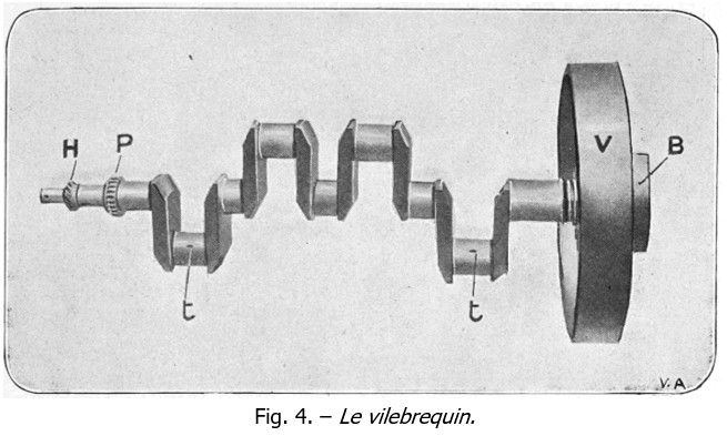
The connecting rod, like the crankshaft and all the mechanical parts, is made of BND steel, which has made it possible to make them as light as possible. They have a double T-section. The crankshaft (fig. 4) rests on five bearings, and the lubrication of the connecting rod ends and heads is carried out under high pressure.
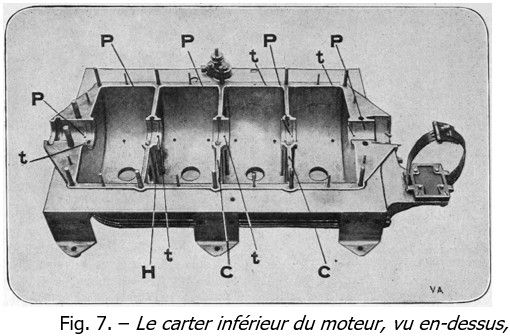
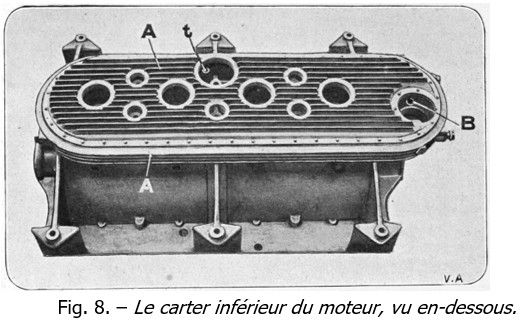
For this purpose, a gear pump (fig. 5) contained in a cylindrical body draws oil through a tube in the lower engine crankcase. This oil is filtered through filter 3 and cooled by the numerous fins on the bottom of the sump (fig. 8). The pump has a conical section that fits into the conical housing in the lower crankcase, thus forming a hermetic seal. Its axis is vertical and it is driven by the same shaft that drives the camshafts. It pumps the oil through the ducts drilled in the partitions of the lower crankcase to the crankshaft bearings and from there, through the inside of the crankshaft, to the crankpins and connecting rod heads.
The oil is kept at a certain level in the crankcase; if it exceeds this level, a hand pump located next to the mechanic can be used to send the excess oil to the reservoir or, conversely, to the crankcase if it is low.
Cooling is provided by a centrifugal pump (Fig. 5) and a Mégevet radiator. Note the pump mount, which is perforated to make it as light as possible. The pump shaft is positioned transversally at the front of the engine and also drives the magneto. This is a Bosch high-voltage, single-spark magneto, which supplies one spark plug per cylinder, located at the top of the cylinder head between the valves.
The carburetor is a new Claudel model, which has proved to be absolutely wonderful. Consider that this 175 HP engine does not consume 24 liters per 100 kilometers, that its acceleration and speed are lightning fast, and that from a standing start it can reach 165 kilometers per hour in 1,000 meters! And I can cite another fact: at Ventoux, Boillot, fearing differences in carburetion due to variations in altitude, had installed an additional air intake that he planned to open at the bottom of the hill and gradually close as he climbed. However, on his first attempt, he realized that this precaution was unnecessary and that his carburetion was perfect at all altitudes, so that this device remained unused during the ascent of the hill. Is this not further irrefutable proof of the value of the Claudel carburetor?
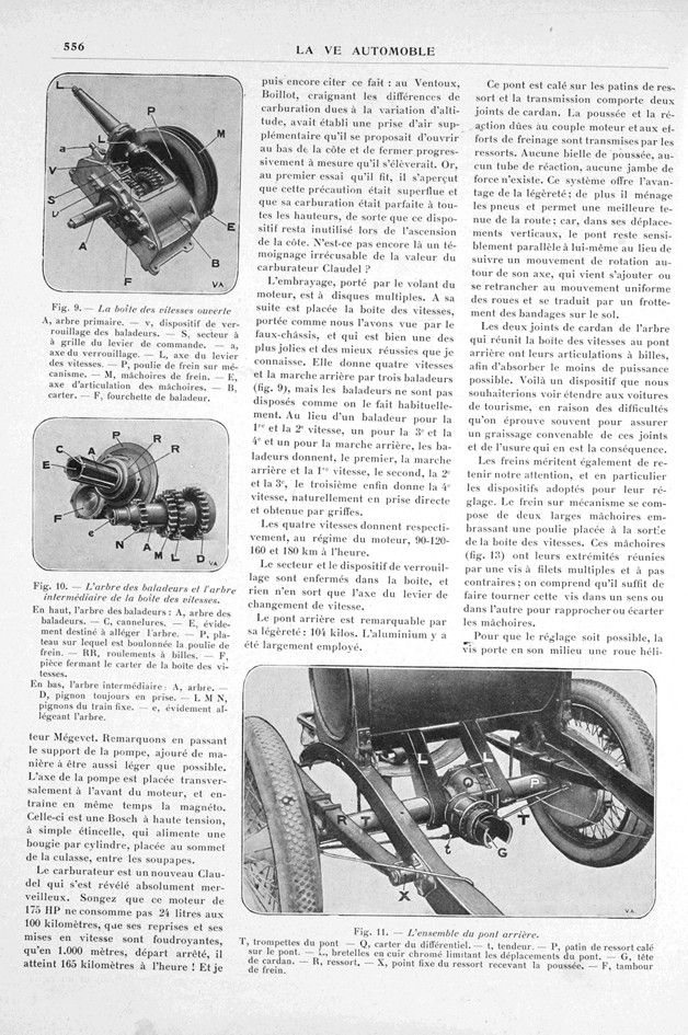
The clutch, driven by the engine flywheel, is a multi-disc type. Behind it is the gearbox, supported, as we have seen, by the subframe, which is one of the most attractive and successful I have ever seen. It has four speeds and reverse gear via three shifters (fig. 9), but the shifters are not arranged in the usual way. Instead of one shifter for 1st and 2nd gear, the third shifter gives 4th gear, naturally in direct drive and obtained by claws.
The four speeds give, respectively, at engine speed, 90-120-160 and 180 km per hour.
The sector and the locking device are enclosed in the box, and nothing protrudes except the gear shift lever shaft.
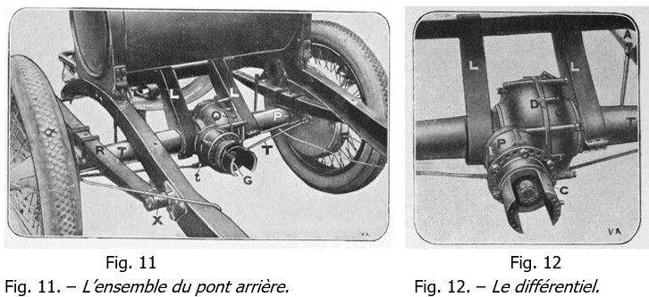
The rear axle is remarkably light, weighing just 104 kg. Aluminum has been used extensively in its construction.
This point is fixed to the spring pads and the transmission has two universal joints. The thrust and reaction caused by the engine torque and braking forces are transmitted by the springs. There are no thrust rods, reaction tubes or struts. This system offers the advantage of lightness; it also protects the tires and improves road holding, because in these vertical movements, the axle remains essentially parallel to itself instead of rotating around its axis, which adds to or subtracts from the uniform movement of the wheels and results in friction between the tires and the ground.
The two cardan joints of the shaft connecting the gearbox to the rear axle have ball joints in order to absorb as little power as possible. This is a feature that we would like to see extended to passenger cars, given the difficulties often encountered in ensuring proper lubrication of these joints and the resulting wear and tear.
The brakes also deserve our attention, particularly the devices used to adjust them. The brake mechanism consists of two large jaws that grip a pulley located at the output of the gearbox. These jaws (fig. 13) are connected at their ends by a screw with multiple threads and opposite pitches; it is clear that turning this screw in either direction is sufficient to bring the jaws closer together or further apart.
To enable adjustment, the screw has a helical wheel fitted in the middle and a loose part N to which the lever controlled by the rod t is attached. This loose part has a screw that meshes with the helical wheel and can be turned by hand using the small knurled wheel V. If brake adjustment is required due to brake shoe wear, simply turn the knurled wheel V to act on screw F via the helical wheel and bring the brake shoes closer to the drum.
This brake is foot-operated. The handbrake acts on the rear wheel drums via inner segments controlled by two cables, and it is the length of these cables that is adjusted to adjust the brake. These two cables are attached to two parts that can slide along the axis of the hand lever and are joined by a screw with a reverse thread. Turning this screw brings the two sliding parts closer together and consequently pulls on the ends of the cables, which brings the brake shoes closer to the drums. It should be noted that these two adjustments can be made while the vehicle is in motion, without removing the floor, through notches provided for this purpose. This is valuable because of the harsh conditions to which these components are subjected.
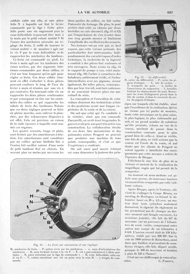
The four long, flat springs are slowed by friction dampers. These dampers consist of a collar that a connecting rod linked to the axle causes to oscillate around a small drum attached to the chassis. By tightening or loosening a nut on the two parts of the collar, the braking intensity can be varied. In addition, the rear axle was connected to the chassis by two chrome-plated leather straps (fig. 11 and 12) which prevented it from moving too far away and limited the amplitude of the springs‘ oscillations
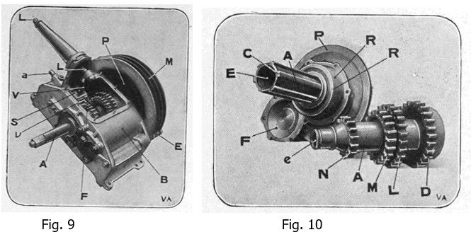
Our readers will have seen from this brief overview that this car has some very interesting features. Apart from its technical characteristics, the quest for lightness has led to some very curious and intricately crafted parts. We have seen (fig. 5) the water pump mount, and now (fig. 10) we see the splined shaft of the balancers, which is completely hollowed out, and the intermediate shaft with its gears, which is also hollowed out. Such parts, remarkable for their craftsmanship, are very expensive and would not be found on a production car.
The design and execution of this car are indicative of skilled technicians and practitioners with long experience of the road and racing.
We know that the man who drove it to victory, along with his teammate Zuccarelli, had outlined its basic design and played a very active role in its construction. The close collaboration between these two skilled mechanics and the powerful Peugeot factories could only produce a machine that was remarkable in every way, and this was confirmed by experience.
We also know how resoundingly successful it has been, demonstrating the soundness of the principles on which it was founded, as well as the excellence of its execution. Let no one speak of a monster here; all of this mechanics is the soundest, most logical, and most rational there is, and many of the solutions it presents, developed with racing in mind, deserve to be incorporated into everyday construction for the greater good of the latter. This proves once again the old axiom that racing is the school of the road, and there is no doubt that Peugeot customers will benefit from the lessons that the brand has learned from the Dieppe race.
Let us congratulate them once again on their victory and, above all, on the creation of the magnificent machine that enabled them to win.
As we go to press, this valiant car has just won further laurels.
After Dieppe and Ventoux, it has just won the Coupe Hénon at the Boulogne meeting, covering the flying kilometer in 28.4/5 seconds with an engine in which only three cylinders were working, as the strict rules did not allow it to change a dirty spark plug at the last minute. On the third day, it averaged 167 km/h over a 7-kilometer course of varied terrain, including a 1-kilometer ramp with an 8% gradient. The previous record was 138 km/h, set by a 200 HP car. On the 1,600-meter Biancthun hill, which was as tough as Gaillon and had numerous bends, it started from a standstill, averaged almost 100 km/h, and finished at over 125 km/h!
It is these figures that I want to focus on.
Charles Faroux.
Photo captions.
Fig. 1. – The cylinder block, intake side.
-C: cylinder block. -A: intake ports. -E: Notch cut into the bottom of the cylinders for the connecting rod to pass through. –S1: intake valves. –S2: exhaust valves. –G: Stud bolts securing the camshaft covers above the valves. –D: Water outlet. –T: Vertical shaft controlling the camshaft gears.
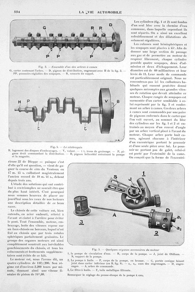
Fig. 2. – The cylinder block, exhaust side.
-C: cylinder block. -O: water inlet ports. -T: vertical shaft controlling the camshaft gears. –K: housing containing the timing gears. –H: pinion meshing with the two camshaft pinions. –S1: intake valves. –S2: exhaust valves. –G: studs securing the camshaft housing above the valves. –Q: exhaust manifold.
Fig. 3. – Assembly of one of the camshafts.
-G: housing containing the shaft. -D: timing gear, meshing with H in Fig. 2. -PP: adjustable valve tappets. –R: return springs.
Fig. 4. – The crankshaft.
-B: clutch disc housing. -V: flywheel. –t t: lubrication holes. –P: spur gear controlling the timing. –H: helical gear driving the pump and magneto.
Fig. 5. – Some auxiliary engine components.
1: Water circulation pump. -R: Pump body. -J: Oldham seal. –S: Pump support. – 2: Oil pump. –P: Pump body, made of bronze. –C: conical seal in lower casing (at B, fig. 8). –a1, a2: gear shafts. –D: gears. –A: drive shaft. 3: oil filter. –F: metal filter mesh.
Note the gland packing adjustment on the water pump.
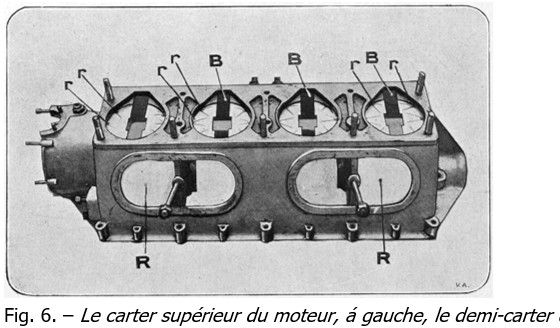
Fig. 6. – The upper engine casing, on the left, the timing cover, on the right, the flywheel bearing. -R: large inspection ports providing access to the connecting rod heads. –B: connecting rod passage. –r: lubrication grooves collecting oil flowing down from the cylinders.
Fig. 7. – The lower engine casing, seen from above, with the magneto support on the right. -P P: crankshaft bearings. –t t: lubrication holes. –C C: vertical partitions supporting the bearings. –H: oil duct in the thickness of the partition.
Fig. 8. – The lower crankcase, viewed from below.
-A: fins used to cool the oil. –t: end of the oil pump suction pipe. –B: conical housing for the oil pump.
Fig. 9. – The gearbox open.
-A: shaft, primary. -v: device for locking the rocker arms. -S: control lever grid section. -a: locking pin. -L: gear lever pin. -P: brake pulley on mechanism. -M: brake shoes. -E: jaw articulation pin. -B: casing. -F: selector fork.
Fig. 10. – The selector shaft and the intermediate shaft of the gearbox.
At the top, the shift shaft: -A: shift shaft. -C: splines. -E: recess to lighten the shaft. -P: plate to which the brake pulley is bolted. -RR: ball bearings. -F: part closing the gearbox housing.
At the bottom, the intermediate shaft: -A: shaft. -D: pinion always in mesh. -L M N: fixed gear pinions. -e: recess to lighten the shaft.
Fig. 11. – The entire rear axle assembly.
-T: axle trumpets. -Q: differential housing. -P: spring pad wedged on the axle. -L: chrome-plated leather straps limiting axle movement. -G: cardan head. -R: spring. -X: fixed point of the spring receiving the thrust. -F: brake drum.
Fig. 12. – The differential.
-D: differential housing. -P: drive pinion housing. -C: cardan head. -T: axle trumpet. -A: suspension shock absorber connecting rods. -L: straps limiting axle movement. Note the lightening holes drilled in the cardan head and in the cover of the drive pinion housing.
Fig. 13. – The brake on the mechanism and adjustment.
-M: brake shoes. -P: pads riveted to the shoes. -a: shoe articulation axle. -B: axles forming nuts with screw F. -F: screw with reverse thread and multiple threads. -N: part driven by the control rod t. -H: helical wheel fitted on screw F. -V: handwheel driving a screw engaged with wheel H. -t: control triangle.