


Text and jpegs by courtesy of hathitrust.org www.hathitrust.org, compiled by motorracinghistory.com
The Automobile, Vol. XXXIV (34), No. 19, May 11, 1916
1916 Racing Cars at Sheepshead
Fast Time Made in Practice by Sunbeam, Maxwell, Peugeot, Crawford and Delage-Technical Details of the Late Arrivals
NEW YORK CITY, May 9 – Day by day the activity on the Sheepshead Bay track is increasing, and about the line of garages beneath the curved sides of the great 2-mile bowl there is a hum of excitement and preparation for the opening of the racing season of 1916. On the track Christiaens in his Sunbeam, Billy Chandler in his Crawford, Ralph Mulford in the Peugeot, Rickenbacker and Henderson in Maxwells, and Miller in the Mulford Special are already trying out their mounts in preparation for the event of May 13.
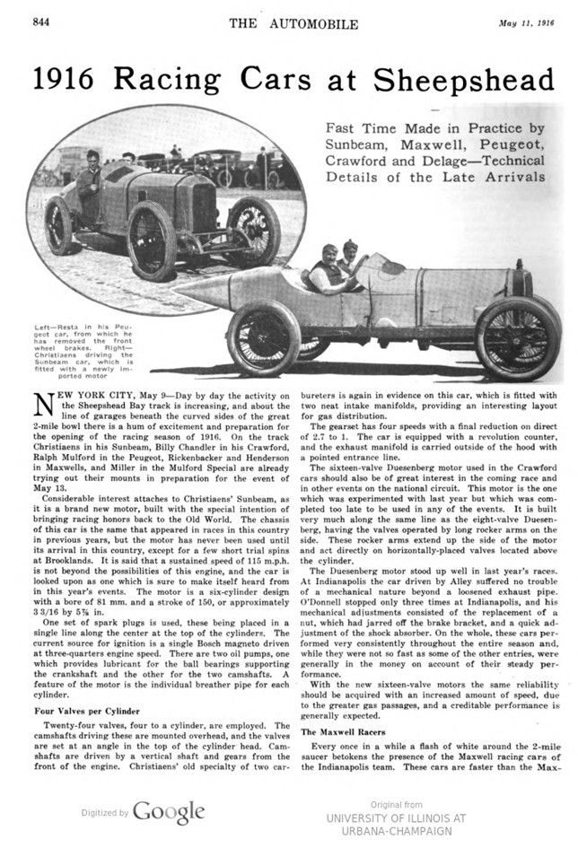
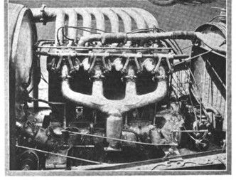
Considerable interest attaches to Christiaens‘ Sunbeam, as it is a brand new motor, built with the special intention of bringing racing honors back to the Old World. The chassis of this car is the same that appeared in races in this country in previous years, but the motor has never been used until its arrival in this country, except for a few short trial spins at Brooklands. It is said that a sustained speed of 115 m.p.h. is not beyond the possibilities of this engine, and the car is looked upon as one which is sure to make itself heard from in this year’s events. The motor is a six-cylinder design with a bore of 81 mm. and a stroke of 150, or approximately 3 3/16 by 5 7/8 in.
One set of spark plugs is used, these being placed in a single line along the center at the top of the cylinders. The current source for ignition is a single Bosch magneto driven at three-quarters engine speed. There are two oil pumps, one which provides lubricant for the ball bearings supporting the crankshaft and the other for the two camshafts. A feature of the motor is the individual breather pipe for each cylinder.
Four Valves per Cylinder
Twenty-four valves, four to a cylinder, are employed. The camshafts driving these are mounted overhead, and the valves are set at an angle in the top of the cylinder head. Camshafts are driven by a vertical shaft and gears from the front of the engine. Christiaens‘ old specialty of two car- bureters is again in evidence on this car, which is fitted with two neat intake manifolds, providing an interesting layout for gas distribution.
The gearset has four speeds with a final reduction on direct of 2.7 to 1. The car is equipped with a revolution counter, and the exhaust manifold is carried outside of the hood with a pointed entrance line.
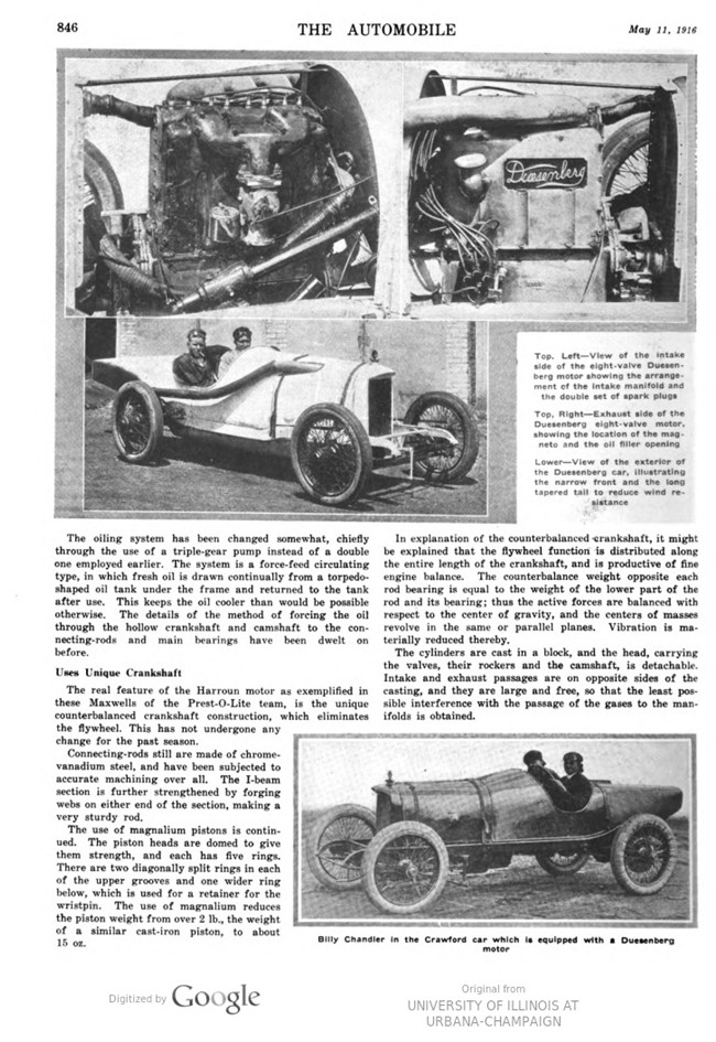
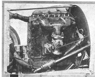
The sixteen-valve Duesenberg motor used in the Crawford cars should also be of great interest in the coming race and in other events on the national circuit. This motor is the one which was experimented with last year, but which was completed too late to be used in any of the events. It is built very much along the same line as the eight-valve Duesenberg, having the valves operated by long rocker arms on the side. These rocker arms extend up the side of the motor and act directly on horizontally-placed valves located above the cylinder.
The Duesenberg motor stood up well in last year’s races. At Indianapolis the car driven by Alley suffered no trouble of a mechanical nature beyond a loosened exhaust pipe. O’Donnell stopped only three times at Indianapolis, and his mechanical adjustments consisted of the replacement of a nut, which had jarred off the brake bracket, and a quick adjustment of the shock absorber. On the whole, these cars per- formed very consistently throughout the entire season and, while they were not so fast as some of the other entries, were generally in the money on account of their steady performance.
With the new sixteen-valve motors the same reliability should be acquired with an increased amount of speed, due to the greater gas passages, and a creditable performance is generally expected.
The Maxwell Racers
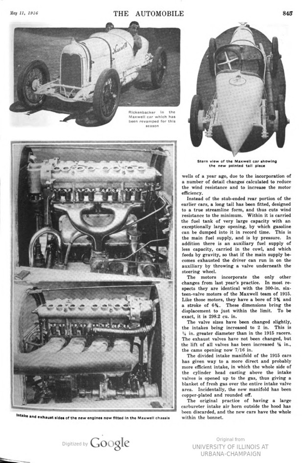
Every once in a while a flash of white around the 2-mile saucer betokens the presence of the Maxwell racing cars of the Indianapolis team. These cars are faster than the Maxwells of a year ago, due to the incorporation of a number of detail changes calculated to reduce the wind resistance and to increase the motor efficiency.
Instead of the stub-ended rear portion of the earlier cars, a long tail has been fitted, designed to a true streamline form, and thus cuts wind resistance to the minimum. Within it is carried the fuel tank of very large capacity with an exceptionally large opening, by which gasoline can be dumped into it in record time. This is the main fuel supply, and is by pressure. In addition, there is an auxiliary fuel supply of less capacity, carried in the cowl, and which feeds by gravity, so that if the main supply becomes exhausted the driver can run in on the auxiliary by throwing a valve underneath the steering wheel.
The motors incorporate the only other changes from last year’s practice. In most respects they are identical with the 300-in. sixteen-valve motors of the Maxwell team of 1915. Like those motors, they have a bore of 3 3/4 and a stroke of 6 3/4. These dimensions bring the displacement to just within the limit. To be exact, it is 298.2 cu. in.
The valve sizes have been changed slightly, the intakes being increased to 2 in. This is 1/4 in. greater diameter than in the 1915 racers. The exhaust valves have not been changed, but the lift of all valves has been increased 1/8 in., the cams opening now 7/16 in.
The divided intake manifold of the 1915 cars has given way to a more direct and probably more efficient intake, in which the whole side of the cylinder head casting above the intake valves is opened up to the gas, thus giving a blanket of fresh gas over the entire intake valve area. Incidentally, the new manifold has been copper-plated and rounded off.
The original practice of having a large carbureter intake air horn outside the hood has been discarded, and the new cars have the whole within the bonnet.
The oiling system has been changed somewhat, chiefly through the use of a triple-gear pump instead of a double one employed earlier. The system is a force-feed circulating type, in which fresh oil is drawn continually from a torpedo- shaped oil tank under the frame and returned to the tank after use. This keeps the oil cooler than would be possible otherwise. The details of the method of forcing the oil through the hollow crankshaft and camshaft to the connecting-rods and main bearings have been dwelt on before.
Uses Unique Crankshaft
The real feature of the Harroun motor as exemplified in these Maxwells of the Prest-O-Lite team, is the unique counterbalanced crankshaft construction, which eliminates the flywheel. This has not undergone any change for the past season.
Connecting-rods still are made of chrome-vanadium steel and have been subjected to accurate machining overall. The I-beam section is further strengthened by forging webs on either end of the section, making a very sturdy rod.
The use of magnalium pistons is continued. The piston heads are domed to give them strength, and each has five rings. There are two diagonally split rings in each of the upper grooves and one wider ring below, which is used for a retainer for the wristpin. The use of magnalium reduces the piston weight from over 2 lb., the weight of a similar cast-iron piston, to about 15 oz.
In explanation of the counterbalanced crankshaft, it might be explained that the flywheel function is distributed along the entire length of the crankshaft, and is productive of fine engine balance. The counterbalance weight opposite each rod bearing is equal to the weight of the lower part of the rod and its bearing; thus the active forces are balanced with respect to the center of gravity, and the centers of masses revolve in the same or parallel planes. Vibration is materially reduced thereby.
The cylinders are cast in a block, and the head, carrying the valves, their rockers and the camshaft, is detachable. Intake and exhaust passages are on opposite sides of the casting, and they are large and free, so that the least possible interference with the passage of the gases to the manifolds is obtained.
Although there are four complete cars, all in shape to make fast time, it is the intention to use only two of them in any race, holding the other two back for emergencies. In addition to the two completed cars held in reserve there is a very complete supply of spare parts and a thorough system of shipping and storing of parts so that they will be on hand when needed. One of the features of this preparedness program includes a combination motor stand and shipping crate; another, a parts bench, which becomes the parts locker for transportation. Altogether Rickenbacher, the team manager, has made very thorough plans for a successful campaign.
Mulford Special Withdraws
The Mulford Special was out on the track without its complete body, but is now withdrawn due to motor trouble. The motor in this car disclosed little from an exterior view. It is a square block in appearance, having four cylinders 3.98 by 6, giving a piston displacement of 299 cu. in. The valves are operated by vertical rocker arms. Everything is being done at the present time to make this car faster. In the last Sheepshead Bay race the Mulford Special was flagged at the 274th mile.
The Erwin Special has been out on the track for a few short trial spins but has had a little trouble with the engine, probably due to the fact that the bearings have been set up too tight. The engine is the same as the Erwin of last year, while the chasis is new although of similar design to the former one. The car is made by the Erwin Motor Machine Co., Philadelphia, Pa., and has a bore of 4 and a stroke of 5 15/16 in. The cylinders are L-head, cast in pairs, with the intake valves in the head and the exhaust valves on the left. All the valves, however, are operated from one camshaft. Rudge-Whitworth wheels with 33 by 5-in. tires are being used in practice. The wheelbase of the car is 108 in.
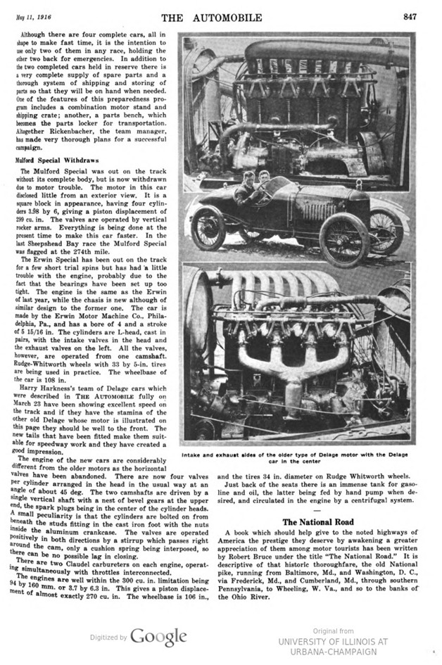
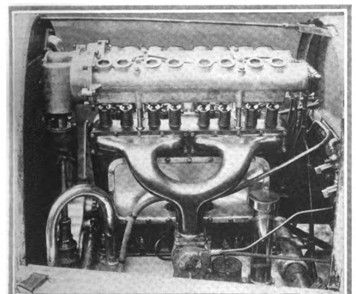
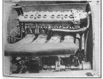
Harry Harkness’s team of Delage cars which were described in THE AUTOMOBILE fully on March 23 have been showing excellent speed on the track and if they have the stamina of the other old Delage whose motor is illustrated on this page they should be well to the front. The new tails that have been fitted make them suit- able for speedway work and they have created a good impression.
The engine of the new cars are considerably different from the older motors as the horizontal valves have been abandoned. There are now four valves per cylinder arranged in the head in the usual way at an angle of about 45 deg. The two camshafts are driven by a single vertical shaft with a nest of bevel gears at the upper end, the spark plugs being in the center of the cylinder heads. A small peculiarity is that the cylinders are bolted on from beneath the studs fitting in the cast iron foot with the nuts inside the aluminum crankcase. The valves are operated positively in both directions by a stirrup which passes right around the cam, only a cushion spring being interposed, so there can be no possible lag in closing.
There are two Claudel carbureters on each engine, operating simultaneously with throttles interconnected.
The engines are well within the 300 cu. in. limitation being 94 by 160 mm. or 3.7 by 6.3 in. This gives a piston displacement of almost exactly 270 cu. in. The wheelbase is 106 in., and the tires 34 in. diameter on Rudge Whitworth wheels.
Just back of the seats there is an immense tank for gasoline and oil, the latter being fed by hand pump when desired, and circulated in the engine by a centrifugal system.
Photo captions.
Page 844.
Left-Resta in his Peugeot car, from which he has removed the front wheel brakes.
Right- Christiaens driving the Sunbeam car, which is fitted with a newly imported motor
Page 845.
Rickenbacker in the Maxwell car which has been revamped for this season
Intake and exhaust sides of the new engines now fitted in the Maxwell chassis
Stern view of the Maxwell car showing the new pointed tail piece
Page 846.
Duesenberg
Top. Left-View of the intake side of the eight-valve Duesenberg motor showing the arrangement of the intake manifold and the double set of spark plugs
Top, Right-Exhaust side of the Duesenberg eight-valve motor, showing the location of the magneto and the oil filler opening
Lower-View of the exterior of the Duesenberg car, illustrating the narrow front and the long-tapered tail to reduce wind resistance
Billy Chandler in the Crawford car which is equipped with a Duesenberg motor
Page 847.
Intake and exhaust sides of the older type of Delage motor with the Delage car in the center