


In tis article, Pierre Maillard describes an important new feature on the all-metal Rudge-Whitworth wheel for 1913. This develoment, a simpler locking device, was a requirement from all-day practice. The ralatively long hub required a cost- and labor intensive activities. Now, by introducing some clearance on the nut- and the hubs threads. It may take some time to understand the mechanism behind this (just as happened to me) but then you’ll see the genious behind this feature.
With the authorisation of Bibliothèque national francais, gallica.bnf.fr. Text and photos compiled by motorracingistory.com, Translation by DeepL.com.
Omnia, Revue pratique de Locomotion, Volume 7, No. 363, Décember 14, 1912
THE RUDGE-WHITWORTH DETACHABLE METAL WHEEL, 1913 MODEL
We have already had the pleasure of publishing here (No. 339) a study on the Rudge-Whitworth detachable wheel and how it works. There is therefore no need to repeat the detailed description of this wheel here, nor to dwell again on the specific design features that enabled its creators to revolutionize the metal wheel industry.
However, Rudge-Whitworth has just created a new wheel model for 1913. While retaining a family resemblance to its predecessors, it differs from them in one important improvement.
The few criticisms that could be levelled at previous Rudge-Whitworth wheels were the considerable width of their hubs, which made them difficult to fit, and their prohibitive price for many.
These two drawbacks stemmed from the system used to lock the wheel onto its false hub: a system that was absolutely secure and automatic, but required a large number of parts that were costly to manufacture and adjust, and was also very bulky.
The only desirable improvement was therefore to simplify the locking system. The problem was a difficult one, since, while simplifying the system, it was important not to compromise safety, but rather to try to reinforce it if possible. The engineers at Rudge-Whitworth solved it completely, and in a manner that does them great credit.
The new wheel consists of only three parts, all three of which are very simple in shape: the wheel itself, with a fluted hub on the inside; the false hub (which contains the ball bearings and is mounted on the car in place of the ordinary hub), fluted on the outside; and the clamping nut that holds the wheel in place on the false hub.
And that’s it. Each of the parts described above is complete; the simplicity of their shape is such that the hub, false hub, and nut can be made (apart from the fluting, of course) entirely on the lathe and mounted as they are for use.
But… but, you might say, this is too simple! A detachable wheel must meet certain specific requirements: first, it must not be able to come off without the owner’s consent; second, it must never stick to the hub when you want to remove it. In the old Rudge-Witworth, the first condition was achieved by two locks, and for the second, the locking nut, when unscrewed, pulled on the wheel, which was forced to come off. Here, none of that is the case! Why?
However, it’s all there! You just have to know where to look to see it.
Let’s look at the locking mechanism first. The hub is centered on the false hub by two conical surfaces, as shown in the attached cross-section. One of the surfaces (on the inside) is between the hub and the false hub; the other (on the outside) is between the hub and the nut. To this end, the nut is hollowed out with a conical groove that fits exactly onto the end of the hub, which is shaped in the same way. So far, everything is very simple. But a small detail, which is worth pointing out, will reveal some of the system’s major original features. Here it is: the nut’s thread has a certain amount of play in relation to the hub’s thread. This means that the two threads are very loose in relation to each other.
This is not a good condition for a nut! That is the first thought that comes to mind.
A nut that is very loose on its thread will come undone. Not at all! logic tells us. In this particular case, not only does it not come undone, but it tightens by itself as the car rolls. Another little bug to look for! Mechanics are full of them. Let’s try to add this one to the collection.

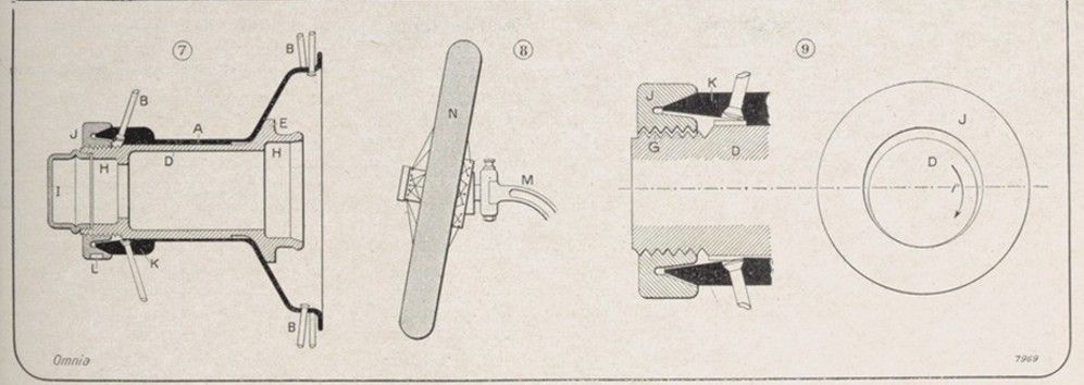
First, let us assume that the nut is not completely tightened. The hub is not centered on the false hub, since it is the nut that performs this function. The wheel will therefore be in the same condition as an ordinary wheel with play on its spindle; it will tilt from bottom to top toward the center of the chassis (figure 8). The nut is thus forced to move upward and will bear on its thread only at the bottom (figure 9). These last three figures are deliberately exaggerated to make the explanation clearer. In the last one, we see the hub and nut offset upward; they have only one real point of contact, located at the bottom.
Now suppose that the hub rotates in the direction of the arrow. The nut will rotate with it, but there will still only be one point of contact at the bottom, so that Figure 9 remains true for any moment of the rotation. During one complete turn of the wheel, all points of the hub will therefore come into contact with the nut; but, as the nut is slightly larger than the hub, the points of contact on the nut will not cover its entire circumference.
In other words, after one complete turn, the nut will lag behind the hub. By how much? By an arc equal to the difference between the two circumferences, that of the hub and that of the nut.
As the nut lags behind the hub, if the hub has a screw thread in the same direction as its rotation, the nut will screw onto it. If the thread were in the opposite direction, the nut would unscrew. This is mathematical. This automatic screwing movement of the nut is not indefinite. It is more pronounced when the eccentricity is greater; but, on the other hand, as the tightening increases, the eccentricity decreases, so that the wheel ends up being perfectly centered and the tightening stops.
Practice has perfectly confirmed this theory. A car equipped with the new wheels, whose nuts are simply tightened by hand, is started up. After five hundred meters, the nuts are so tight that a wrench is needed to unscrew them!
It remains to examine the second condition that a well-made detachable wheel must fulfill: the impossibility of bonding between the two hubs. Here, the nut does not cause the wheel to come off, because it is unnecessary. The splines on the hub and the false hub are only used for driving, and their teeth do not engage fully, any more than those of two gears meshing together. Contact between the two hubs therefore only occurs on the two conical parts mentioned above, one of which is on the nut. Once the nut is removed, it is not the other, very obtuse cone that could cause sticking! The wheel always comes off without difficulty.
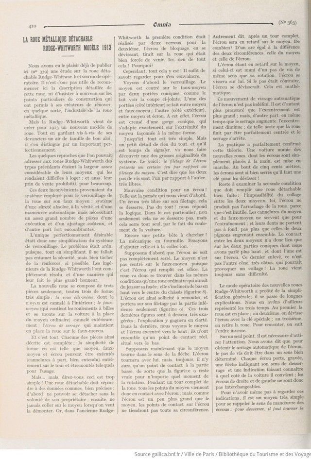
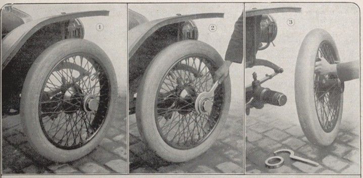
The operating procedure for the new Rudge-Whitworth wheels has benefited from general simplification; there is no need for lengthy explanations. We have illustrated the three stages. In the first, the wheel is in place; in the second, the nut is unscrewed with the special wrench; in the third, the wheel is removed. To reassemble, follow the steps in reverse order.
There is one point that needs to be highlighted. We have said that, in order to tighten the nut automatically, the thread must be in a specific direction. Each nut has an arrow engraved on it indicating the direction in which it should be loosened and an indication of which side of the car it is suitable for; the right and left nuts are therefore not interchangeable.
To avoid having to look at these indications, there is a very simple way to remember the direction in which the nuts should be turned: to loosen them, turn the wrench in the direction of rotation of the wheel. There is no way to make a mistake.
As for maintenance, it is limited to keeping the outside of the false hub and the inside of the main hub greased.
And now, the only objection that the new wheels might provoke: if they tighten automatically when moving forward, what will happen when moving backward?
Obviously, loosening may occur. We say may, but not will. If this happens, the first forward movement will restore things to their original state. So much for this objection.
The value of the new Rudge-Whitworth wheels has been confirmed by long and repeated road tests. Even after prolonged use, they are never found to be loose, even if a careless driver has tightened their nuts with a distracted hand.
Their extreme simplicity, their small size and also—why not say it?—their modest price will quickly make them popular. They are recruiting: they have many followers among motorists who love comfort and progress.
Pierre MAILLARD.
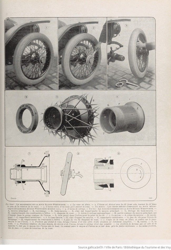
Top: HOW TO HANDLE THE RUDGE-WHITWORTH WHEEL. — 1. The wheel in place.— 2. The nut is unscrewed with the wrench (to do this, turn the wrench in the direction of the wheel’s rotation). = 3. Once the nut has been removed, all that remains is to remove the wheel.
Middle: THE THREE PARTS OF THE 1913 RUDGE-WHITWORTH DETACHABLE METAL WHEEL. — 4. The tightening nut.
Bottom: HOW THE RUDGE-WHITWORTH WHEEL WORKS. — A, main hub. — B, spokes. — D, false hub. — E, cone on which the main hub rests. — G, threading of the false hub. — H, ball bearing locations. — I, wheel cap. — J, self-locking nut. — K, conical part of the main hub, which engages in the conical groove of the nut. — L, hole drilled in the nut for the wrench. — 5. The hub. — A, hub body. — B, spokes. — C, internal splines. = 6. The false hub. — E, hub support cone. — F, external splines. — G, screw thread for the locking nut. — H, ball bearing location. — I, wheel cap screw thread. = 7. Cross-section of the wheel, in place, centered on the false hub and nut. — 8. Position of the wheel when the nut is not tightened. (This position is greatly exaggerated). — M, axle. — N, wheel. = 9. Relative positions of the false hub, hub, and nut when not fully tightened. — The position of the wheel, which is that shown in figure 8, causes the hub to pull the nut upwards; contact between the hub and the nut therefore only occurs at the lower part. — The same position, seen from the front. — f, direction of rotation of the wheel.