


Charles Faroux decribes in tis article, the most important specifics of the detachable, all steel wheel of R.A.F. Definicely not being the Britisch air force, the name stands for la Société des Roues Amovibles Francaise.; the Company for French detachable wheels. At the 1912 Grand Prix at Dieppe, these wheels had quite an influence on racing car speed and behaviour, compared to the then common wooden cannon wheels. Lower weight, faster acceleration and better braking, as well as lower tyre temperatures were the most significant characteristcs of these all-steel wheels.
With authorisation of Conservatoire numérique des Arts et Métiers (Cnum) – https://cnum.cnam.fr
Text and photos compiled by motorracinghistory.com, Translation by DeepL.com
La Vie Automobile Volume 10. — N° 563. – Saturday July 13, 1912.
The detachable R.A.F. wheel
At a time when the Dieppe Grand Prix has definitively and spectacularly confirmed the superiority of metal wheels over wooden ones, we thought it would be interesting to share with our readers a description of one of the most successful examples of these wheels, the R.A.F. wheel manufactured by the Société des Roues Amovibles Française.
We will not attempt to explain the advantages of the metal wheel here, as our readers are already familiar with them. They know that it weighs less than a wooden wheel (and, above all, that the weight is distributed differently, mainly to the hub, which reduces the moment of inertia); that its elasticity and the greater cooling it provides to the tires give it valuable economic qualities. They know that its removability minimizes the hassle of changing tires, with two or three minutes of easy work replacing the tedious and exhausting chore of yesteryear, which can be done at the stage in the best conditions of comfort, ease, and tranquility.
Let’s look at the facts of the problem, and then we’ll outline the solutions offered by the R.A.F. wheel.
The front and rear wheels must be identical so that they can be replaced by spare wheels. The wheel must be quick to mount and held in place by a lock that is completely secure. Neither road shocks, vibrations, nor even the rubbing or contact of any object should have any influence on it. It must also indicate at a glance whether it is open or closed. Finally, the wheel must be perfectly centered, with no runout or play, and the drive wheels must be rigorously secured.
Here is how these considerations are implemented. A false hub is mounted on each of the front and rear axles.
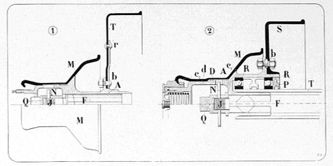
This hub supports the ball bearings and, for the rear wheels, the brake drums. These false hubs are therefore different depending on their location and, for the drive wheels, depending on how the wheel is driven. Fig. 1 shows a front wheel assembly, while Fig. 2 shows two rear wheel assemblies for cars with cardan shafts. In one, the wheel is attached to the end of the differential shaft, which is both a drive shaft and a support shaft, while in the other it is supported by two ball bearings on the rear axle tube T.
The hub carriers, as I said, are different depending on their purpose, but they have exactly the same external profile. The actual hub M (Figs. 1 and 2) is placed on each of them, forming the removable wheel together with the metal spokes and the rim.
The false hub has a conical part at c1 that acts as a stop for the hub. The hub is held in place by the nut that screws onto the threaded part of the false hub and presses firmly against the conical surface of the hub, which is clamped between the two cones c and ci and is held perfectly in place with no play.
It is centered by the cylindrical part of the false hub, which is rigorously calibrated and fits exactly.
It is driven by the teeth D of the false hub, which engage with corresponding teeth on the hub. These two large teeth are extremely robust and have tooth entries similar to those of gear shift sprockets, in order to facilitate wheel installation.
Once the hub is placed on the false hub and the nut is tightened fully, these two parts are completely joined together in all planes and form a single unit. We can therefore see that to fit the wheel, all you need to do is tighten nut L G,2 and unscrew it to remove the wheel. This nut can rotate relative to the hub, but is fixed to it in the direction of its axis, thus forming a wheel pull. As you can see, it couldn’t be simpler.
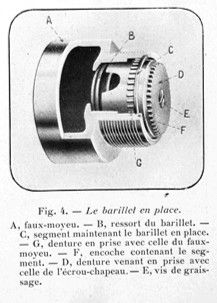
However, in order for this system to be completely safe, the nut must be locked so that it cannot be loosened under any accidental influence. To this end, the false hub contains a barrel I) (fig. 1 and 4). This barrel, which is pushed outwards by a strong spring, has two sets of teeth: one engages with a set of teeth G (fig. 1) on the inner surface of the false hub, which secures the barrel and the false hub together; the other K engages with a set of inner teeth cut into the nut cap. In this way, the nut, being secured to the barrel which is held in place by its engagement in the false hub, is held absolutely secure and cannot come loose for any reason whatsoever.
This locking device is remarkable for its simplicity and effectiveness, and offers many advantages. First, it is perfectly symmetrical with respect to the axis and completely balanced. Secondly, it is completely sealed, and neither dust, mud, rainwater nor washing water can penetrate inside and interfere with its operation. A quick glance is enough to see whether or not the lock is engaged, depending on whether or not the barrel is flush with the outer face of the nut cap. The barrel has around forty teeth, making it very easy to engage. No external cause can unlock the safety device, as spring B, with a force of 50 kilograms, holds it in place.
Finally, there are no protrusions that could catch or become damaged when the wheel encounters an obstacle.
To hold the barrel in place and prevent the spring from throwing it out, a groove F (fig. 4) cut into the false hub receives a segment that rests on the teeth of the barrel.
The procedure for mounting and removing the wheel is therefore obvious. To remove it, push the barrel inwards, compressing the spring, so as to disengage its teeth from those of the nut cap, then unscrew the nut. The wheel will come out by itself.
To reassemble, place the wheel on the false hub and screw the nut tight while holding the barrel down.
Then allow the barrel to return to its place under the pressure of its spring, and if its teeth and those of the cap do not engage, increase the tightness slightly with a quick jerk until the teeth engage.
To facilitate this operation, R. A. F. has developed a special wrench, shown in Fig. 7. This wrench, whose hexagonal opening fits exactly onto the six sides of the cap nut, has two latches, C and D, which can be operated by hand and engage in the groove of the nut. A small lever A is pressed down and turned to the right, releasing a screw E that pushes back the barrel, allowing the wheel to be removed. When reassembling, with the wheel in place and the nut screwed on, simply turn A to the left to allow the barrel to return to its locked position. As can be seen, the operation is as quick as it is simple.
The false hub, fixed to the spindle, should not be removed. The bearings are lubricated by removing screw E (fig. 4) and screwing in an oil or grease syringe instead. However, if you wish to remove the false hub to inspect the ball bearings or brake segments, here is how to do it.
Screw the small device shown (fig. 8), called an extractor, onto the false hub. By pushing in screw A, the barrel is pushed back, and with a pointed tool (pin punch, file tip, etc.), the segment is compressed and pushed out of its groove. When the extractor is unscrewed, the barrel, segment, and spring fall into the operator’s hand. Remove the nut holding the false hub in place, replace the extractor, and, by screwing screw A in fully, it will rest on the end of the spindle and function as a wheel puller. The reverse procedure is used to put everything back in place.
Those of my readers who have not been put off by this somewhat dry description will realize that these operations are infinitely quicker and easier to perform than to describe.
It takes just one or two minutes to replace one wheel with another. The special wrench is not essential; if you don’t have one, you can still remove the wheel. Simply push down hard on the barrel to drive it in, for example with the handle of a hammer pressed against your chest or held by an assistant, while loosening the cap nut with a large wrench.
* * *
I will not dwell any longer on this device, whose ingenuity and efficiency my readers will surely have appreciated. But before concluding, I would like to show them the extent to which the creators of the R.A.F. wheel pursued the study of the smallest details with a concern for mechanical perfection.
Take, for example, the rim and the spokes. The rim is not just any wooden wheel rim, it is a special rim made of high-strength steel, reinforced where the spoke nuts will be attached. To ensure that the nuts bear normally across their entire surface, the rim is not milled, which would weaken it, but stamped to form small bosses (fig. 1), which are then drilled in the direction the spoke is to be inserted. The spoke therefore works strictly in tension, without undergoing any bending stress.
The design of the spokes has been carefully thought out, leading to the adoption of four spoke systems, shown in T1, T2, T3, and T4, which can withstand all the stresses that the wheel is likely to experience. The spokes, made of Martin steel resistant to 110 kg, are reinforced at both ends with an R shape (fig. 9). The hub has no flanges, which avoids bending the spoke at a right angle at its end and thus subjecting it to shear stress. The bend is very slight, and the head of the spoke rests on a conical part D in a countersink in the hub, so that it fits correctly over its entire surface. Milling was used here because of the greater thickness of the hub. It is clear how much thought has been given to every detail
The execution is in no way inferior to the design.
The workshops, which are entirely new, contain only the most modern machine tools. The false hub and barrel are turned from the bar by automatic lathes; the hub, made of high-strength steel, is stamped.
All parts are carefully calibrated and checked to ensure absolute interchangeability. Would you like an example of the care taken in every operation?
The threading of the spoke ends is not achieved by a die, which would cut the metal fibers and reduce its strength, but by rolling between two plates moving back and forth. The metal is, in a way, wrought and stretched, and its fibers remain intact.
The wheel is then assembled, the spokes are tensioned to the desired level and tested by sound. It is checked both for balance and for the regularity of its shape. And here we perhaps touch on one of the reasons why wooden wheels wear out tires more quickly than metal wheels.
A wooden wheel is never perfectly round. The different points on the circumference of a wheel that is not strictly circular move at different linear speeds, with the result that the tires roll on the ground with slippage, which causes damage. Metal wheels, on the other hand, are perfectly circular and remain so indefinitely, despite the weather. This is certainly one of the secrets of their superiority.
Finally, the whole thing is oven-enameled, which gives it a more elegant and durable finish than paint.
The wheel, treated in this way, is a true mechanical part, made with the same care and precision as the rest of our chassis. This is one of the vestiges of the old horse-drawn carriage that is disappearing, much to the delight of drivers. Let us not regret it, and let us hope that, where it still exists, we will soon see progress similar to that which the R.A.F. Company has brought us in the field of wheels.
Charles Faroux.
Photo captions.
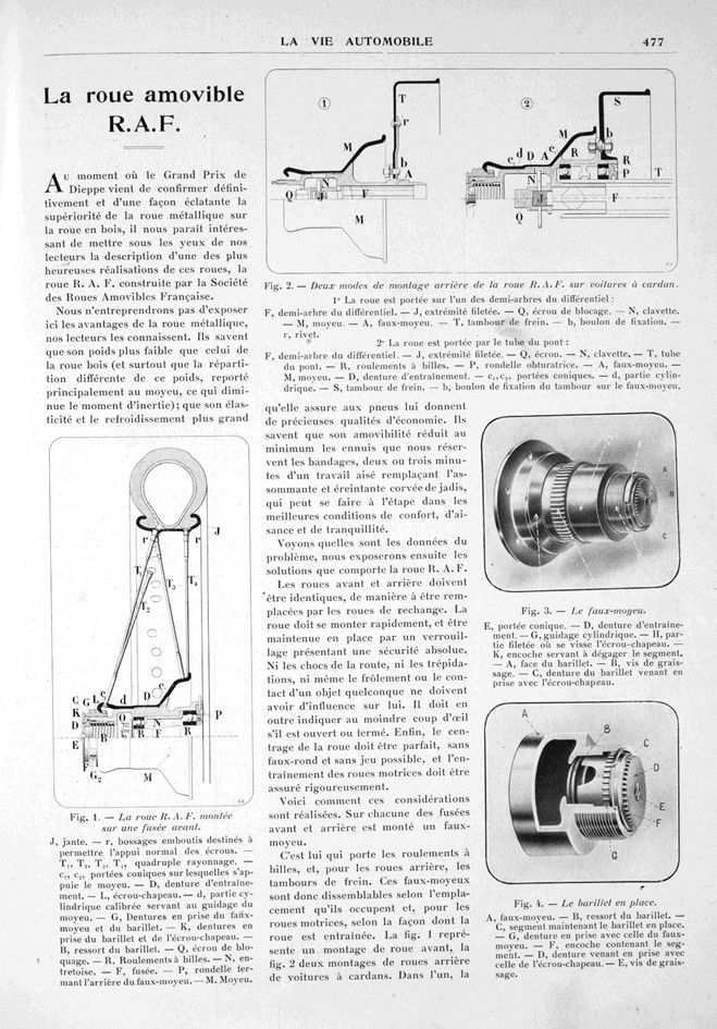
Fig. 1. — The R.A.F. wheel molded onto a front hub.
J, rim. — r, stamped bosses designed to allow normal support for the nuts. — T1, T2, T3, T4, quadruple spokes. — c1, c2, conical bearings on which the hub rests. — D, drive teeth. — L, cap nut. — d, calibrated cylindrical part used to guide the hub. — G, teeth engaged with the false hub and barrel. — K, meshing teeth of the barrel and cap nut. — B, barrel spring. — Q, locking nut. — R. Ball bearings. — N, spacer. — F, spindle. — P, washer closing the rear of the false hub. — M. Hub.
Fig. 2. — Two methods of rear mounting of the R.A.F. wheel on cardan wings.
1° The wheel is mounted on one of the differential half-shafts:
F, differential half-shaft. — J, threaded end. — Q, locking nut. — N, key. — M, hub. — A, false hub. — T, brake drum. — b, fixing bolt. — r, rivet.
2° The wheel is supported by the axle tube:
F, differential half-shaft. — J, threaded end. — Q, nut. — N, key. — T, axle tube. — R, ball bearings. — P, sealing washer. — A, false hub. — M, hub. — D, drive teeth. — c15c2, conical surfaces. — d, cylindrical part. — S, brake drum. — b, bolt for fixing the drum to the false hub.
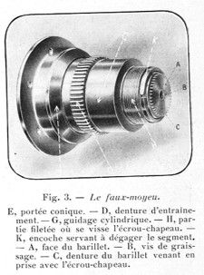
Fig. 3. — The false hub.
E, conical bearing. — D, drive gear.
— G, cylindrical guide. — H, threaded part where the cap nut is screwed on. — K, notch used to release the segment. — A, face of the barrel. — B, lubrication screw. — C, teeth on the barrel that engage with the cap nut.
Fig. 4. — The barrel in place.
A, false hub. — B, barrel spring. — C, segment holding the barrel in place. — G, teeth engaging with those of the false hub. — F, notch containing the segment. — D, teeth engaging with those of the cap nut. — E, grease screw.
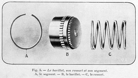
Fig. 5. — The barrel, its spring, and its segment.
A, the segment. — B, the barrel. C, — the spring.
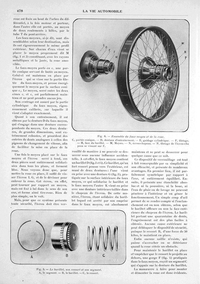
Fig. 6. — Assembly of the false hub and the wheel.
C, conical bearing. — D, drive teeth. — Ë, cylindrical guide. — F, thread. — H, barrel face. — M, hub. — N, cap nut. — P, thread of the cap nut screwing onto F.
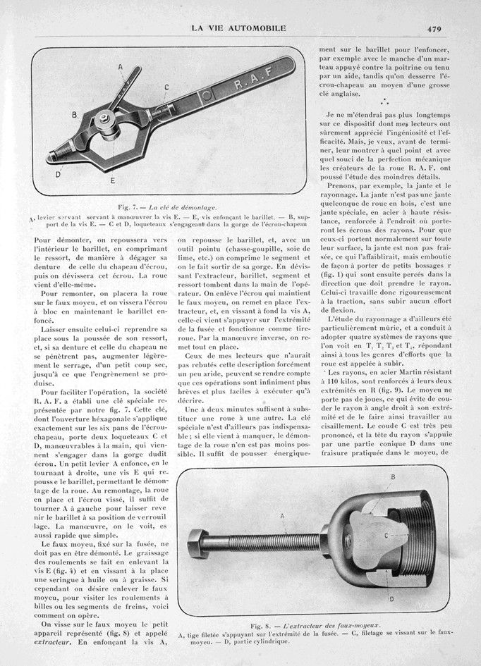
Fig. 7. — The mold release key.
A, lever used to operate screw E. — E, screw pressing down the barrel. — B, screw support E. — C and D, latches engaging in the cap nut groove
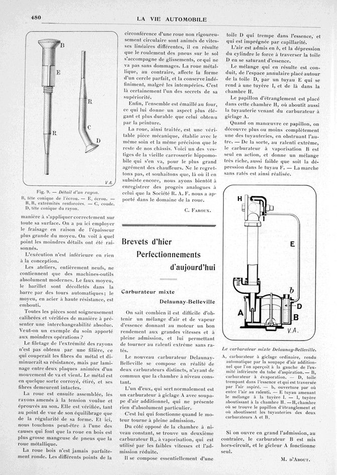
Fig. 8. — False hub extractor.
A, threaded rod resting on the end of the spindle. — C, thread screwing onto the false hub. — D, cylindrical part.
Fig. 9. — Detail of a spoke.
B, conical head of the nut. — E, nut. — R, H, reinforced ends. — C, elbow. D, conical head of the spoke.